Nissan Maxima Owners Manual: MOD system operation
The MOD system will turn on automatically under the following conditions:
- When the shift lever is in the R (Reverse) position.
- When vehicle speed decreases below approximately 6 mph (10 km/h) and the camera screen is displayed.
Front and bird's-eye views
The MOD system operates in the following conditions when the camera view is displayed:
- When the shift lever is in the P (Park) or N (Neutral) position and the vehicle is stopped, the MOD system detects moving objects in the bird's-eye view. The MOD system will not operate if the outside mirrors are moving in or out, in the stowed position, or if either front door is opened.
- When the shift lever is in the D (Drive) position and the vehicle speed is below approximately 6 mph (10 km/h), the MOD system detects moving objects in the front view.
Rear and bird's-eye views
- When the shift lever is in the R (Reverse)
position and the vehicle speed is below approximately
6 mph (10 km/h), the MOD system
detects moving objects in the rear view.
The MOD system will not operate if the trunk is open.
The MOD system does not detect moving objects in the front-side view. The MOD icon is not displayed on the screen when in this view.
When the MOD system detects moving objects near the vehicle, a chime will be heard and a yellow frame will be displayed on the view where the objects are detected. While the MOD system continues to detect moving objects, the yellow frame continues to be displayed.
Rear and front-side views
NOTE:
While the RCTA chime (if so equipped) is beeping, the MOD system does not chime
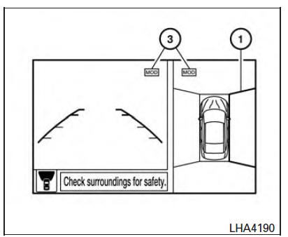
In the bird's-eye view, the yellow frame 1 is displayed on each camera image (front, rear, right, left) depending on where moving objects are detected.
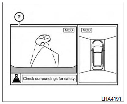
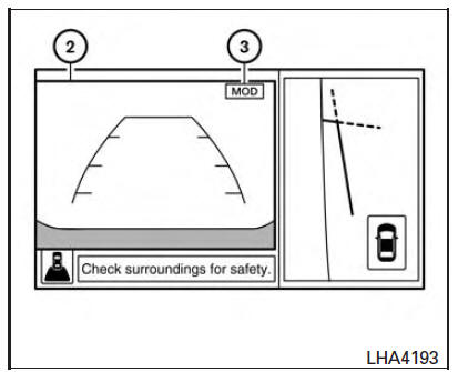
The yellow frame 2 is displayed on each view in the front view and rear view modes.
A blue MOD icon 3 is displayed in the view where theMODsystem is operative. A grayMOD icon is displayed in the view where the MOD system is not operative.
If theMODsystem is turned off, theMODicon 3 is not displayed
Turning MOD on and off
To turn the MOD system on or off, press and hold the CAMERA button for more than 2 seconds.
 Moving Object Detection (MOD) (if so equipped)
1. CAMERA button
WARNING
Failure to follow the warnings and instructions
for proper use of the Moving
Object Detection system could result in
serious injury or death.
The MOD system i ...
 MOD system limitations
WARNING
Listed below are the system limitations for
MOD. Failure to operate the vehicle in
accordance with these system limitations
could result in serious injury or death.
Do not use the MOD ...
Other materials:
Steering wheel
WARNING
Do not adjust the steering wheel while
driving. You could lose control of your
vehicle and cause an accident.
Do not adjust the steering wheel any
closer to you than is necessary for
proper steering operation and comfort.
The driver's air bag inflates with great
force. If ...
Excessive ABS function operation frequency
Diagnosis Procedure
1.CHECK START
Check front and rear brake force distribution using a brake tester.
2.CHECK FRONT AND REAR AXLE
Make sure that there is no excessive play in the front and rear axles.
3.CHECK WHEEL SENSOR AND SENSOR ROTOR
Check the following:
Wheel sensor installation for ...
Engine maintenance (VQ35DE)
DRIVE BELTS
DRIVE BELTS : Checking Drive Belts
Idler pulley
Drive belt
Power steering oil pump
Drive belt auto-tensioner
Crankshaft pulley
Idler pulley
A/C compressor
Generator
Indicator
New drive belt range
Possible use range
View D
Engine front
WA ...
Nissan Maxima Owners Manual
- Illustrated table of contents
- Safety-Seats, seat belts and supplemental restraint system
- Instruments and controls
- Pre-driving checks and adjustments
- Monitor, climate, audio, phone and voice recognition systems
- Starting and driving
- In case of emergency
- Appearance and care
- Do-it-yourself
- Maintenance and schedules
- Technical and consumer information
Nissan Maxima Service and Repair Manual

0.0105