Nissan Maxima Service and Repair Manual: P0181 FTT sensor
Description
The fuel tank temperature sensor is used to detect the fuel temperature inside the fuel tank. The sensor modifies a voltage signal from the ECM. The modified signal returns to the ECM as the fuel temperature input. The sensor uses a thermistor which is sensitive to the change in temperature. The electrical resistance of the thermistor decreases as temperature increases.
<Reference data>
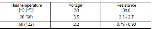
*: These data are reference values and are measured between ECM terminals 95 (Fuel tank temperature sensor) and 104 (sensor ground).
DTC Logic
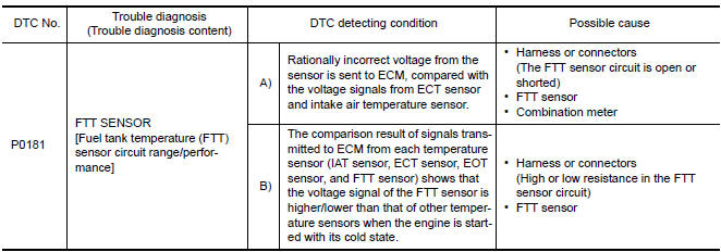
DTC DETECTION LOGIC
DTC CONFIRMATION PROCEDURE
1.INSPECTION START
2.PRECONDITIONING
If DTC CONFIRMATION PROCEDURE has been previously conducted, always perform the following procedure before conducting the next test.
- Turn ignition switch OFF and wait at least 10 seconds.
- Turn ignition switch ON.
- Turn ignition switch OFF and wait at least 10 seconds.
3.PERFORM DTC CONFIRMATION PROCEDURE FOR MALFUNCTION A-I
- Turn ignition switch ON and wait at least 10 seconds.
- Check 1st trip DTC.
4.CHECK ENGINE COOLANT TEMPERATURE
With CONSULT
- Select "COOLAN TEMP/S" in "DATA MONITOR" with CONSULT.
- Check "COOLAN TEMP/S" value.
With GST
Follow the procedure "With CONSULT" above.
5.PERFORM DTC CONFIRMATION PROCEDURE FOR MALFUNCTION A-II
With CONSULT
- Cool engine down until "COOLAN TEMP/S" is less than 60C (140F).
- Wait at least 10 seconds.
- Check 1st trip DTC.
With GST
Follow the procedure "With CONSULT" above.
6.PERFORM COMPONENT FUNCTION CHECK (FOR MALFUNCTION B)
Perform component function check. Refer to EC-271, "Component Function Check".
NOTE: Use the component function check to check the overall function of the FTT sensor circuit. During this check, a 1st trip DTC might not be confirmed.
7.PRECONDITIONING
If DTC CONFIRMATION PROCEDURE has been previously conducted, always perform the following procedure before conducting the next test.
- Turn ignition switch OFF and wait at least 10 seconds.
- Turn ignition switch ON.
- Turn ignition switch OFF and wait at least 10 seconds.
TESTING CONDITION:
- Before performing the following procedure, do not add fuel.
- Before performing the following procedure, check that fuel level is between 1/4 and 4/4.
- Before performing the following procedure, confirm that battery voltage is 11 V or more at idle.
8.PERFORM DTC CONFIRMATION PROCEDURE B
- Start engine and let it idle for 60 minutes.
- Move the vehicle to a cool place. NOTE: Cool the vehicle in an environment of ambient air temperature between −10C (14F) and 35C (95F).
- Turn ignition switch OFF and soak the vehicle for 12 hours.
CAUTION:
Never turn ignition switch ON during soaking.
NOTE: The vehicle must be cooled with the food open.
- Start engine and let it idle for 5 minutes or more. CAUTION: Never turn ignition switch OFF during idling.
- Check 1st trip DTC.
Component Function Check
1.CHECK FUEL TANK TEMPERATURE (FTT) SENSOR
- Turn ignition switch OFF.
- Disconnect fuel level sensor unit and fuel pump harness connector.
- Remove fuel level sensor unit. Refer to FL-6, "Removal and Installation".
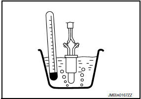
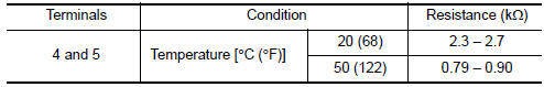
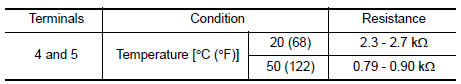
- Check resistance between fuel level sensor unit and fuel pump terminals by heating with hot water as shown in the figure.
2.CHECK INTERMITTENT INCIDENT
Check intermittent incident.
Diagnosis Procedure
1.INSPECTION START
Confirm the detected malfunction (A or B).
2.CHECK GROUND CONNECTION
- Turn ignition switch OFF.
- Check ground connection E9.
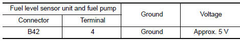
3.CHECK FUEL TANK TEMPERATURE SENSOR POWER SUPPLY CIRCUIT
- Turn ignition switch OFF.
- Disconnect "fuel level sensor unit and fuel pump" harness connector.
- Turn ignition switch ON.
- Check the voltage between "fuel level sensor unit and fuel pump" harness connector and ground.
4.DETECT MALFUNCTIONING PART
Check the following.
- Harness connectors B10, E29
- Harness for open or short between ECM and "fuel level sensor unit and fuel pump"
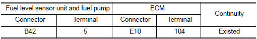
5.CHECK FUEL TANK TEMPERATURE SENSOR GROUND CIRCUIT FOR OPEN AND SHORT
- Turn ignition switch OFF.
- Disconnect ECM harness connector.
- Check the continuity between "fuel level sensor unit and fuel pump" harness connector and ECM harness connector.
- Also check harness for short to ground and short to power
6.DETECT MALFUNCTIONING PART
Check the following.
- Harness connectors B1, M6
- Harness connectors E30, M1
- Harness for open or short between "fuel level sensor unit and fuel pump" and ECM
7.CHECK FUEL TANK TEMPERATURE SENSOR
8.CHECK INTERMITTENT INCIDENT
Component Inspection
1.CHECK FUEL TANK TEMPERATURE SENSOR
- Turn ignition switch OFF.
- Remove fuel level sensor unit. Refer to FL-6, "Removal and Installation".
- Check resistance between "fuel level sensor unit and fuel pump" terminals by heating with hot water as shown in the figure.
 P0172, P0175 fuel injection system function
DTC Logic
DTC DETECTION LOGIC
With the Air/Fuel Mixture Ratio Self-Learning Control, the actual mixture
ratio can be brought closely to the
theoretical mixture ratio based on the mixture ratio f ...
 P0182, P0183 FTT sensor
Description
The fuel tank temperature sensor is used to detect the fuel temperature
inside the fuel tank. The sensor modifies a voltage signal from
the ECM. The modified signal returns to the ...
Other materials:
Periodic maintenance
FOR USA AND CANADA
FOR USA AND CANADA : Introduction of Periodic Maintenance
The following tables show the normal maintenance schedule. Depending upon
weather and atmospheric conditions,
varying road surfaces, individual driving habits and vehicle usage, additional
or more frequent maintenan ...
U1300 AV comm circuit
Description
U1300 is indicated when malfunction occurs in communication signal of multi
AV system. Indicated simultaneously,
without fail, with the malfunction of control units connected to AV control unit
with communication line.
Determine the possible malfunction cause from the table bel ...
C1147, C1148, C1149, C1150 USV/HSV line
Description
USV1, USV2 (CUT VALVE)
The cut valve shuts off the normal brake fluid path from the master cylinder,
when VDC/TCS is activated.
HSV1, HSV2 (SUCTION VALVE)
The suction valve supplies the brake fluid from the master cylinder to the
pump, when VDC/TCS is activated.
DTC Logic
DTC D ...
Nissan Maxima Owners Manual
- Illustrated table of contents
- Safety-Seats, seat belts and supplemental restraint system
- Instruments and controls
- Pre-driving checks and adjustments
- Monitor, climate, audio, phone and voice recognition systems
- Starting and driving
- In case of emergency
- Appearance and care
- Do-it-yourself
- Maintenance and schedules
- Technical and consumer information
Nissan Maxima Service and Repair Manual

0.0069