Nissan Maxima Service and Repair Manual: USB connector
Removal and Installation
REMOVAL
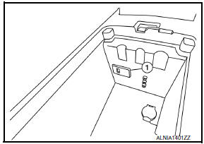
- Remove the center console assembly. Refer to IP-14, "Removal and Installation".
- Push the pawl from the back of the center console to remove the USB interface (1).
INSTALLATION
Installation is in the reverse order of removal
 Audio display unit
Removal and Installation
Audio display unit bracket
Audio display unit
Cluster lid D
Multifunction switch
Audio display unit bracket screws
Audio display unit screws
Metal Cl ...
 Aux in jack
Removal and Installation
REMOVAL
Remove the center console assembly. Refer to IP-14, "Removal and
Installation".
Remove the auxiliary input jacks screws (A) and auxiliary input ...
Other materials:
License lamp finisher
Exploded View
License lamp finisher
Trunk request switch connector
Grommet Clip
Removal and Installat
REMOVAL
Remove the trunk lid finisher. Refer to INT-36, "Removal and
Installation".
Disconnect the harness connector (1) from the trunk request
switch.
Remove the ...
Brake precautions
The brake system has two separate hydraulic
circuits. If one circuit malfunctions, you will still
have braking at two wheels.
Vacuum assisted brakes
The brake booster aids braking by using engine
vacuum. If the engine stops, you can stop the
vehicle by depressing the brake pedal. However,
gre ...
DLC branch line circuit
Diagnosis Procedure
1.CHECK CONNECTOR
Turn the ignition switch OFF.
Disconnect the battery cable from the negative
terminal.
Check the terminals and connectors of the data
link connector for damage, bend and loose connection
(connector side and harn ...
Nissan Maxima Owners Manual
- Illustrated table of contents
- Safety-Seats, seat belts and supplemental restraint system
- Instruments and controls
- Pre-driving checks and adjustments
- Monitor, climate, audio, phone and voice recognition systems
- Starting and driving
- In case of emergency
- Appearance and care
- Do-it-yourself
- Maintenance and schedules
- Technical and consumer information
Nissan Maxima Service and Repair Manual

0.0062