Nissan Maxima Service and Repair Manual: ABS warning lamp
Description
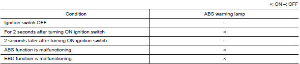
Component Function Check
1.CHECK ABS WARNING LAMP OPERATION
Check that the lamp illuminates for approximately 2 seconds after the ignition switch is turned ON.
Diagnosis Procedure
1.CHECK SELF-DIAGNOSIS
Perform ABS actuator and electric unit (control unit) self-diagnosis.
2.CHECK COMBINATION METER
Check if the indication and operation of combination meter are normal.
Special Repair Requirement
1.ADJUSTMENT OF STEERING ANGLE SENSOR NEUTRAL POSITION
Always perform the neutral position adjustment for the steering angle sensor, when replacing the ABS actuator and electric unit (control unit).
 VDC off switch
Description
VDC OFF switch deactivates (turn OFF) the VDC/TCS function when the VDC OFF
switch is pressed.
Component Function Check
1.CHECK VDC OFF SWITCH OPERATION
Operate the VDC OFF switch an ...
 Brake warning lamp
Description
NOTE:
1: Brake warning lamp will turn on in case of parking brake operation
(when switch is ON) or of brake fluid level switch operation
(when brake fluid is insufficient).
...
Other materials:
Paddle shifter
Exploded View
Steering column assembly
Paddle shifter (shift-down)
Paddle shifter (shift-up)
Removal and Installation
REMOVAL
Park the vehicle on a level surface.
Remove the driver air bag module. Refer to
SR-12, "Expl ...
Center speaker
Removal and Installation
REMOVAL
Remove the center speaker grille, using a suitable tool.
Remove the center speaker screws (A).
Pull out the center speaker (1), disconnect the harness connector
from the center speaker and remove.
INSTALLATION
Installation is in the reverse order of ...
Diagnosis system (AV control unit)
Diagnosis Description
MULTIFUNCTION SWITCH AND PRESET SWITCH SELF-DIAGNOSIS FUNCTION
The ON/OFF operation (continuity) of each switch in the multifunction switch
and preset switch can be checked.
Self-Diagnosis Mode
Press the BACK switch and the
switch of the 8-direction switches with ...
Nissan Maxima Owners Manual
- Illustrated table of contents
- Safety-Seats, seat belts and supplemental restraint system
- Instruments and controls
- Pre-driving checks and adjustments
- Monitor, climate, audio, phone and voice recognition systems
- Starting and driving
- In case of emergency
- Appearance and care
- Do-it-yourself
- Maintenance and schedules
- Technical and consumer information
Nissan Maxima Service and Repair Manual

0.0072