Nissan Maxima Service and Repair Manual: VDC off switch
Description
VDC OFF switch deactivates (turn OFF) the VDC/TCS function when the VDC OFF switch is pressed.
Component Function Check
1.CHECK VDC OFF SWITCH OPERATION
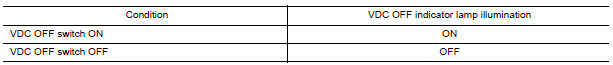
Operate the VDC OFF switch and check that the VDC OFF indicator lamp in the combination meter turns on/ off correctly.
Diagnosis Procedure
1.CHECK VDC OFF SWITCH
Perform VDC OFF switch component inspection
2.CHECK VDC OFF SWITCH HARNESS
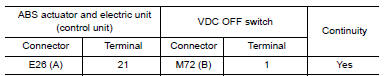
- Disconnect ABS actuator and electric unit (control unit) connector.
- Check continuity between ABS actuator and electric unit (control unit) connector E26 (A) terminal 21 and VDC OFF switch connector M72 (B) terminal 1.
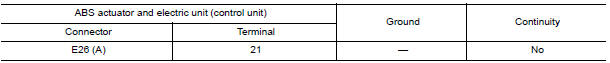
- Check continuity between ABS actuator and electric unit (control unit) connector E26 (A) terminal 21 and ground.
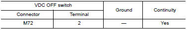
3.CHECK VDC OFF SWITCH GROUND
Check continuity between VDC OFF switch connector M72 terminal 2 and ground.
Component Inspection
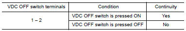
1.CHECK VDC OFF SWITCH
- Turn ignition switch OFF.
- Disconnect VDC OFF switch connector.
- Check continuity between VDC OFF switch terminals
 Parking brake switch
Description
The parking brake switch converts the status of the parking brake pedal to an
electric signal and transmits it to
the combination meter. The combination meter, through CAN communicati ...
 ABS warning lamp
Description
Component Function Check
1.CHECK ABS WARNING LAMP OPERATION
Check that the lamp illuminates for approximately 2 seconds after the
ignition switch is turned ON.
Diagnosis Procedur ...
Other materials:
License lamp finisher
Exploded View
License lamp finisher
Trunk request switch connector
Grommet Clip
Removal and Installat
REMOVAL
Remove the trunk lid finisher. Refer to INT-36, "Removal and
Installation".
Disconnect the harness connector (1) from the trunk request
switch.
Remove the ...
The light reminder warning does not sound
Description
Light reminder warning does not sound even though headlamp is illuminated.
Diagnosis Procedure
1. CHECK COMBINATION SWITCH (LIGHTING AND TURN SIGNAL SWITCH) OPERATION
Check that the headlamps operate normally by operating the combination switch
(lighting and turn signal
switch).
...
Front disc brake
Exploded View of Brake Pads
Inner shim cover
Inner shim
Inner pad
Outer pad
Outer shim
Outer shim cover
Anti-rattle clips
Pad retainers
Molykote AS-880N grease
Molykote 7439 grease
Removal and Installation of Brake Pads
WARNING:
Clean dust on caliper and b ...
Nissan Maxima Owners Manual
- Illustrated table of contents
- Safety-Seats, seat belts and supplemental restraint system
- Instruments and controls
- Pre-driving checks and adjustments
- Monitor, climate, audio, phone and voice recognition systems
- Starting and driving
- In case of emergency
- Appearance and care
- Do-it-yourself
- Maintenance and schedules
- Technical and consumer information
Nissan Maxima Service and Repair Manual

0.006