Nissan Maxima Service and Repair Manual: Front coil spring and strut
Removal and Insallation
REMOVAL
- Remove front wheel and tire using power tool. Refer to WT-60, "Adjustment".
- Remove the wheel sensor harness from the front coil spring and strut. Refer to BRC-102, "Removal and Installation - Front Wheel Sensor".
- Remove the brake hose lock plate.
- Remove the lower strut bolts and nuts. Refer to FSU-13, "Exploded View".
- Remove the front side cover from the strut tower.
- Remove the upper strut bolts and remove the front coil spring and strut from vehicle.
INSPECTION AFTER REMOVAL
Check the front coil spring and strut for any oil leakage or other damage. Replace as necessary.
INSTALLATION
Installation is in the reverse order of removal.
CAUTION: Do not reuse the lower strut nuts.
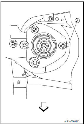
- - Be sure tab (A) on strut mount insulator is positioned as shown.
 : Front
 - - Check wheel alignment. Refer to FSU-6, "Inspection and Adjustment".
Disposal
- Set the front suspension strut horizontally with the piston rod fully extended.
- Drill 2 - 3 mm (0.08 - 0.12 in) hole at the position (
 ) from top as shown to release gas
gradually.
) from top as shown to release gas
gradually.
CAUTION:
- Wear eye protection (safety glasses).
- Wear gloves.
- Be careful with metal chips or oil blown out by the compressed gas.
NOTE:
- Drill vertically in this direction (
 ).
). - Directly to the outer tube avoiding brackets.
- The gas is clear, colorless, odorless, and harmless.

(A) : 20 - 30 mm (0.79 - 1.18 in)
- Position the drilled hole downward and drain oil by moving the piston rod several times.
CAUTION: Dispose of drained oil according to the law and local regulations.

 Transverse link
Removal and Installation
REMOVAL
Remove front wheel and tire using power tool. Refer to WT-60,
"Adjustment".
Remove the knuckle spindle bolt and nut at the transverse link.
Remove the stee ...
Other materials:
Crash zone sensor
Component
Crash zone sensor harness connector
Crash zone sensor
Nut
Front
Removal and Installation
CAUTION:
Before servicing, turn ignition switch OFF, disconnect both
battery terminals and wait at least 3 minutes.
Do not use air tools or electric tools for servicing.
...
Steering switch
Removal and Installation
REMOVAL
Remove the driver airbag module. Refer to SR-12, "Removal and
Installation".
Remove the steering wheel audio control switch screws (A).
Release the steering wheel audio control switch harness clips
(B).
Remove the steering wheel audio control switc ...
P0335 CKP sensor (POS)
Description
The crankshaft position sensor (POS) is located on the oil pan facing
the gear teeth (cogs) of the signal plate. It detects the fluctuation of
the engine revolution.
The sensor consists of a permanent magnet and Hall IC.
When the engine is running, the high and low parts o ...
Nissan Maxima Owners Manual
- Illustrated table of contents
- Safety-Seats, seat belts and supplemental restraint system
- Instruments and controls
- Pre-driving checks and adjustments
- Monitor, climate, audio, phone and voice recognition systems
- Starting and driving
- In case of emergency
- Appearance and care
- Do-it-yourself
- Maintenance and schedules
- Technical and consumer information
Nissan Maxima Service and Repair Manual

0.0066