Nissan Maxima Service and Repair Manual: Camshaft Valve Clearance
Valve Clearance
CHECKING
NOTE:
- Perform inspection as follows after removal, installation or replacement of camshaft or valve related parts, or if there are unusual engine conditions regarding valve clearance.
- Check valve clearance while engine is cold and not running.
- Remove the front air duct with air cleaner case, collectors, hoses, wires, harnesses, and connectors. Refer to EM-24, "Removal and Installation".
- Remove the intake manifold collectors. Refer to EM-25, "Removal and Installation".
- Remove the ignition coils and spark plugs. Refer to EM-42, "Exploded View".
- Remove the rocker covers. Refer to EM-48, "Exploded View".
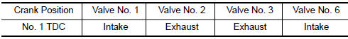
- Set No.1 cylinder at TDC on its compression stroke.
- Align timing indicator with TDC mark (0) on crankshaft pulley.
- Check that the valve lifters on No.1 cylinder are loose and valve lifters on No.4 are tight. If not, turn the crankshaft one full revolution (360) and align as shown.
- Check only the valve lifters as shown.
- Using a suitable tool, measure the clearance between the valve lifter and camshaft.
- Record any valve lifter clearance measurements which are out of
specification. They will be used later to determine the required
replacement valve lifter size.
Valve Clearance for Checking (cold)
Intake : 0.26 - 0.34 mm (0.010 - 0.013 in)
Exhaust : 0.29 - 0.37 mm
(0.011 - 0.015 in)
- Turn crankshaft 240.
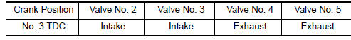
- Set No.3 cylinder at TDC on its compression stroke.
- Check only those valve lifters as shown.
- Turn the crankshaft 240.
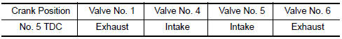
- Set No.5 cylinder at TDC on its compression stroke.
- Check only those valve lifters as shown.
- If all valve lifter clearances are within specification, install the following components. If the valve lifter clearances are out of specification, adjust the valve lifter clearances.
- Intake manifold collectors
- Rocker covers
- All spark plugs
- All ignition coils
VALVE LIFTER ADJUSTING
CAUTION: Adjust valve lifter clearance while engine is cold.
NOTE:
- Perform adjustment by selecting the correct head thickness of the valve lifter (adjusting shims are not used).
- The specified valve lifter thickness is the dimension at normal temperatures. Ignore dimensional differences caused by temperature. Use specifications for hot engine condition to confirm valve lifter clearances.
- Remove the camshaft. Refer to EM-76, "Removal and Installation".
- Remove the valve lifter that was measured as being outside the standard specifications.
- Measure the center thickness of the removed valve lifter using suitable tool as shown.
- Use the equation below to calculate the replacement valve lifter thickness.
Valve lifter thickness calculation equation: t = t1 + (C1 - C2)
t =
thickness of the replacement valve lifter
t1 = thickness of the removed
valve lifter
C1 = measured valve lifter clearance
C2 = standard valve
lifter clearance
- The thickness of the new valve lifter can be identified by the stamp mark on the reverse side (inside the valve lifter).
- Available thickness of the valve lifter (factory setting): 7.88 - 8.40 mm (0.3102 - 0.3307 in), in 0.02 mm (0.0008 in) increments, in 27 sizes (intake/exhaust). Refer to EM-130, "Camshaft".
- Install the selected replacement valve lifter.
- Install the camshaft. Refer to EM-76, "Removal and Installation".
- Rotate the crankshaft a few turns by hand.
- Confirm that the valve lifter clearances are within specification.
- After the engine has been run to full operating temperature, confirm that the valve lifter clearances are within specification.
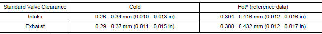
* Approximately 80C (176F)
 Air Cleaner Filter
Removal and Insta
Air duct hose and resonator assembly
Front air duct
Air cleaner case (lower)
Grommets
Air cleaner case mounting bracket
Bracket
Air cleaner filter
Air clea ...
 Compression Pressure
On-Vehicle Service
CHECKING COMPRESSION PRESSURE
Run the engine until it reaches normal operating temperature.
Turn the ignition switch to OFF.
Release fuel pressure. Refer to EC-592, "In ...
Other materials:
Door switch
Exploded View
Door switch
Removal and Installation
REMOVAL
Remove the door switch screw (A).
Disconnect the harness connector from the door switch (1) and
remove
INSTALLATION
Installation is in the reverse order of removal. ...
Electric ignition system
System Diagram
System Description
INPUT/OUTPUT SIGNAL CHART
*1: This signal is sent to the ECM via the CAN communication line.
*2: ECM determines the start signal status by the signals of engine speed and
battery voltage.
SYSTEM DESCRIPTION
Ignition order: 1 - 2 - 3 - 4 - 5 - 6
The ...
Mudguard
Exploded View
Mudguard
Clip C205
Clip CF118
Front
Removal and Installation
REMOVAL
Remove the clips located on the underbody.
Remove the center mudguard front and rear screws.
Remove the rear wind deflector bolt. Refer to EXT-24, "Removal and
Installation".
Release t ...
Nissan Maxima Owners Manual
- Illustrated table of contents
- Safety-Seats, seat belts and supplemental restraint system
- Instruments and controls
- Pre-driving checks and adjustments
- Monitor, climate, audio, phone and voice recognition systems
- Starting and driving
- In case of emergency
- Appearance and care
- Do-it-yourself
- Maintenance and schedules
- Technical and consumer information
Nissan Maxima Service and Repair Manual

0.0056