Nissan Maxima Service and Repair Manual: Compression Pressure
On-Vehicle Service
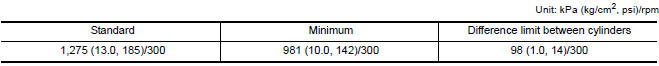
CHECKING COMPRESSION PRESSURE
- Run the engine until it reaches normal operating temperature.
- Turn the ignition switch to OFF.
- Release fuel pressure. Refer to EC-592, "Inspection".
- Remove all six spark plugs.
Refer to EM-12, "Removal and Installation".
- Attach a compression tester to No. 1 cylinder.
- Depress accelerator pedal fully to keep the electric throttle control actuator butterfly-valve wide open to maximize air intake flow.
- Crank the engine and record the highest gauge indication.
- Repeat the measurement on each cylinder (steps 5 - 7).
- Always use a fully-charged battery to obtain specified engine speed.
- If the engine speed is out of the specified range check the battery and recharge as necessary. Check the engine speed again with the battery properly charged.
- If some cylinders have low compression pressure, pour a small amount of engine oil into the spark plug hole of the cylinder to re-check it for compression.
- If the added engine oil improves the compression, piston rings may be worn out or damaged. Check the piston rings and replace if necessary
- If the compression pressure remains at low level despite the addition of engine oil, the valves may be malfunctioning. Check the valves for damage. Replace the valve or valve seat accordingly.
- If two adjacent cylinders have respectively low compression pressure and their compression remains low even after the addition of engine oil, cylinder head gaskets may be leaking, or a valve in adjacent cylinders may be damaged. Inspect and repair as required.
- If the compression pressure is below the minimum value, check the valve clearances and parts associated with the combustion chamber (valve, valve seat, piston, piston ring, cylinder bore, cylinder head, cylinder head gasket). After the checking, measure the compression pressure again.
 Camshaft Valve Clearance
Valve Clearance
CHECKING
NOTE:
Perform inspection as follows after removal, installation or
replacement of camshaft or valve related parts, or if there are unusual
engine conditions rega ...

Other materials:
Pre-inspection for diagnostic
Pre-Inspection for Multi-System Diagnostic
The engine start function, door lock function, power distribution system and
NATS-IVIS/NVIS are closely
related to each other. Narrow down the system in question by performing this
inspection to identify which system
is malfunctioning. For example, ...
Squeak and rattle trouble diagnoses
Work Flow
CUSTOMER INTERVIEW
Interview the customer if possible, to determine the conditions that exist
when the noise occurs. Use the Diagnostic Worksheet during the interview to
document the facts and conditions when the noise occurs and any customer's
comments; refer to RF-64, "Diagnost ...
Diagnosis system (HVAC)
CONSULT Function
CONSULT can display each diagnosis item using the diagnosis test modes as
shown.
CONSULT application items
SELF-DIAGNOSTIC RESULT
Display Item List
*: Perform self-diagnosis under sunshine. When performing indoors, aim a
light (more than 60 W) at sunload sensor, ...
Nissan Maxima Owners Manual
- Illustrated table of contents
- Safety-Seats, seat belts and supplemental restraint system
- Instruments and controls
- Pre-driving checks and adjustments
- Monitor, climate, audio, phone and voice recognition systems
- Starting and driving
- In case of emergency
- Appearance and care
- Do-it-yourself
- Maintenance and schedules
- Technical and consumer information
Nissan Maxima Service and Repair Manual

0.0055