Nissan Maxima Service and Repair Manual: Display unit
Reference Value
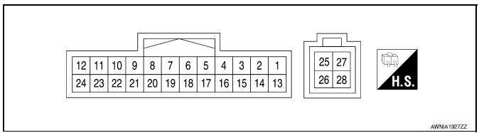
TERMINAL LAYOUT
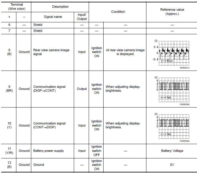
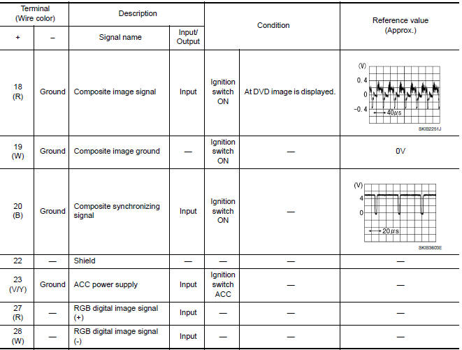
PHYSICAL VALUES
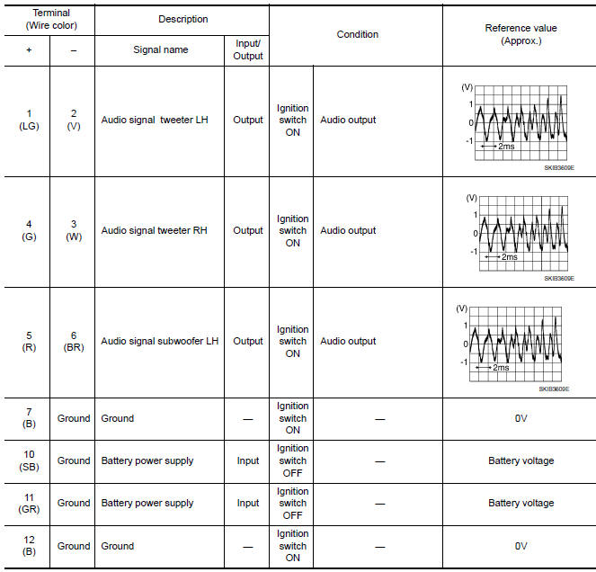
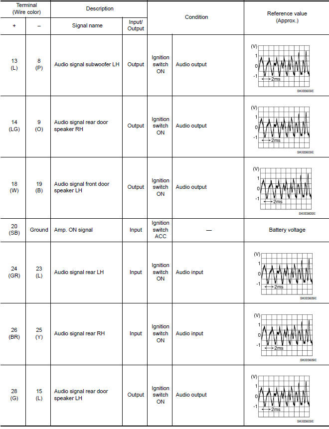
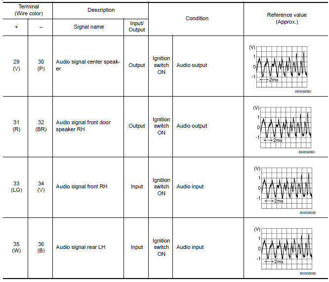
BOSE SPEAKER AMP
Reference Value
TERMINAL LAYOUT
PHYSICAL VALUES
 AV control unit
Reference Value
VALUES ON THE DIAGNOSIS TOOL
CONSULT data monitor item
TERMINAL LAYOUT
PHYSICAL VALUES
DTC Index
SELF-DIAGNOSIS RESULTS DISPLAY ITEM
...
 Wiring diagram
COLOR DISPLAY
Wiring Diagram - With BOSE audio system With Navigation System
...
Other materials:
Inside the vehicle
The maintenance items listed here should be
checked on a regular basis, such as when performing
scheduled maintenance, cleaning the vehicle,
etc.
Accelerator pedal: Check the pedal for smooth
operation and make sure the pedal does not
catch or require uneven effort. Keep the floor mat
away ...
Engine compartment check locations
VQ35DE engine
Engine coolant reservoir
Drive belt location
Engine oil filler cap
Brake fluid reservoir
Air cleaner
Fuse block
Fuse block/Fusible links
Fusible links
Battery
Engine oil dipstick
Radiator cap
Power steering fluid reservoir
Windshield-washer fluid reservo ...
P0171, P0174 fuel injection system function
DTC Logic
DTC DETECTION LOGIC
With the Air/Fuel Mixture Ratio Self-Learning Control, the actual mixture
ratio can be brought closely to the
theoretical mixture ratio based on the mixture ratio feedback signal from A/F
sensor 1. The ECM calculates
the necessary compensation to correct the o ...
Nissan Maxima Owners Manual
- Illustrated table of contents
- Safety-Seats, seat belts and supplemental restraint system
- Instruments and controls
- Pre-driving checks and adjustments
- Monitor, climate, audio, phone and voice recognition systems
- Starting and driving
- In case of emergency
- Appearance and care
- Do-it-yourself
- Maintenance and schedules
- Technical and consumer information
Nissan Maxima Service and Repair Manual

0.0062