Nissan Maxima Service and Repair Manual: Removal and installation
WHEEL HUB
Removal and Installation
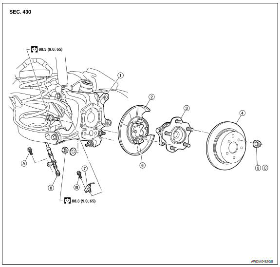
- Knuckle
- Baffle plate
- Wheel hub assembly
- Brake rotor
- Wheel nut
- Anchor block
- Wheel sensor
- Parking brake cable
- Refer to PB-6, "Exploded View".
- Refer to BRC-103, "Removal and Installation - Rear Wheel Sensor".
- Refer to WT-65, "Road Wheel".
REMOVAL
CAUTION: Wheel hub assembly does not require maintenance. If any of the following symptoms are noted, replace the wheel hub assembly.
- A growling noise is emitted from the wheel hub assembly while driving.
- The wheel hub assembly drags or turns roughly.
- Remove the rear wheel and tire using power tool. Refer to WT-60, "Adjustment".
- Remove the brake caliper assembly and brake rotor using power tool. Refer to BR-36, "Removal and Installation of Brake Caliper and Rotor".
- The brake hose does not need to be disconnected from the brake caliper.
CAUTION:
- Suspend the brake caliper assembly using wire, do not stretch the brake hose.
- Do not depress the brake pedal, or the caliper piston will pop out.
- Do not twist the brake hose.
- Remove the rear wheel sensor, then move it away from the wheel hub
assembly. Refer to BRC-103, "Removal and Installation - Rear Wheel
Sensor".
CAUTION: Failure to remove the wheel sensor may result in damage to the sensor wires and the sensor being inoperative. - Remove the wheel hub assembly from knuckle.
INSPECTION AFTER REMOVAL
Check for any deformity, cracks, or damage on the wheel hub assembly, replace if necessary.
INSTALLATION
Installation is in the reverse order of removal.
- Check that the wheel bearings operate smoothly.
- Check that the wheel hub bearing axial end play is within specification.
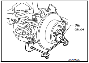
Axial end play : Refer to RAX-8, "Wheel Bearing (Rear)".
- Tighten wheel nut to specification.
SERVICE DATA AND SPECIFICATIONS (SDS)
Wheel Bearing (Rear)

 Periodic maintenance
WHEEL HUB
On-vehicle Service
Check axle and suspension parts for excessive play, wear or damage.
Shake each rear wheel to check for excessive play.
Inspection
Rear Wheel Bearing
...
 Suspension
...
Other materials:
Preparation
PREPARATION
Special Service Tools
The actual shapes of the tools may differ from those illustrated here.
Commercial Service Tools
...
Front fog lamp system
Wiring Diagram
...
U1000 CAN comm circuit
Description
CAN (Controller Area Network) is a serial communication line for real time
application. It is an on-vehicle multiplex
communication line with high data communication speed and excellent error
detection ability. Many electronic
control units are equipped onto a vehicle, and each co ...
Nissan Maxima Owners Manual
- Illustrated table of contents
- Safety-Seats, seat belts and supplemental restraint system
- Instruments and controls
- Pre-driving checks and adjustments
- Monitor, climate, audio, phone and voice recognition systems
- Starting and driving
- In case of emergency
- Appearance and care
- Do-it-yourself
- Maintenance and schedules
- Technical and consumer information
Nissan Maxima Service and Repair Manual

0.0081