Nissan Maxima Service and Repair Manual: Door key cylinder switch
Description
The main power window and door lock/unlock switch detects condition of the door key cylinder switch and transmits to BCM as the LOCK or UNLOCK signal.
Component Function Check
1.CHECK DOOR KEY CYLINDER SWITCH INPUT SIGNAL
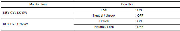
Check KEY CYL UN-SW, KEY CYL UN-SW in "DATA MONITOR" mode for "POWER DOOR LOCK SYSTEM" with CONSULT.
Diagnosis Procedure
1.CHECK DOOR KEY CYLINDER SWITCH INPUT SIGNAL
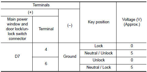
- Turn ignition switch ON.
- Check voltage between main power window and door lock/ unlock switch connector and ground
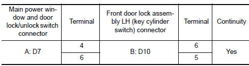
2.CHECK DOOR KEY CYLINDER SIGNAL CIRCUIT
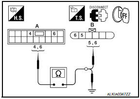
- Turn ignition switch OFF.
- Disconnect main power window and door lock/unlock switch connector and front door lock assembly LH (key cylinder switch) connector.
- Check continuity between main power window and door lock/ unlock switch connector and front door lock assembly LH (key cylinder switch) connector.
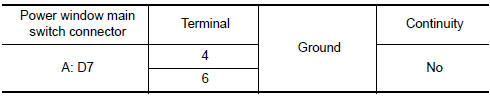
- Check continuity between main power window and door lock/ unlock switch connector and ground.
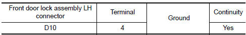
3.CHECK DOOR KEY CYLINDER SWITCH GROUND CIRCUIT
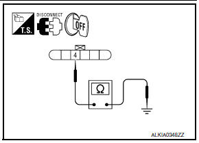
Check continuity between front door lock assembly LH connector and ground.
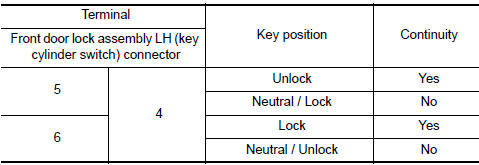
4.CHECK DOOR KEY CYLINDER SWITCH
Check door key cylinder switch
Component Inspection
COMPONENT INSPECTION
1.CHECK DOOR KEY CYLINDER SWITCH
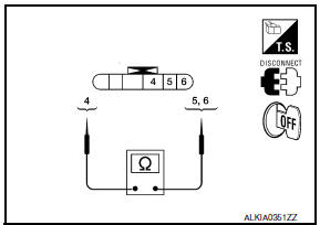
Check front door lock assembly LH (key cylinder switch).
Special Repair Requirement
1. PERFORM INITIALIZATION PROCEDURE
Perform initialization procedure
2. CHECK ANTI-PINCH OPERATION
Check anti-pinch operation
 Door switch
Description
Detects front door open/close condition.
Component Function Check
1.CHECK FUNCTION
With CONSULT
Check front door switches DOOR SW-DR and DOOR SW-AS in Data Monitor mode with
CONSULT ...
 Power window serial link
POWER WINDOW MAIN SWITCH
POWER WINDOW MAIN SWITCH : Description
Main power window and door lock/unlock switch, power window and door
lock/unlock switch RH and BCM
communicate via the power ...
Other materials:
Front door speaker
Description
The audio unit sends audio signals to the front door speakers using the front
door speaker circuits.
Diagnosis Procedure
1.CONNECTOR CHECK
Check the audio unit and speaker connectors for the following:
Proper connection
Damage
Disconnected or loose terminals
...
Rear view camera
Removal and Installation
REMOVAL
Remove the license plate finisher. Refer to EXL-166, "Removal and
Installation".
Remove trunk lid finisher. Refer to INT-36, "Exploded View".
Disconnect the rear view camera connector (B), press the rear
view camera tab (A) and remo ...
Bose speaker amp
Reference Value
TERMINAL LAYOUT
PHYSICAL VALUES
...
Nissan Maxima Owners Manual
- Illustrated table of contents
- Safety-Seats, seat belts and supplemental restraint system
- Instruments and controls
- Pre-driving checks and adjustments
- Monitor, climate, audio, phone and voice recognition systems
- Starting and driving
- In case of emergency
- Appearance and care
- Do-it-yourself
- Maintenance and schedules
- Technical and consumer information
Nissan Maxima Service and Repair Manual

0.0053