Nissan Maxima Service and Repair Manual: Power window serial link
POWER WINDOW MAIN SWITCH
POWER WINDOW MAIN SWITCH : Description
- Main power window and door lock/unlock switch, power window and door lock/unlock switch RH and BCM communicate via the power window serial link.
- The keyless power window down signal is transmitted from BCM to main power window and door lock/ unlock switch and power window and door lock/unlock switch RH.
- The following signals are transmitted from main power window and door lock/unlock switch to power window and door lock/unlock switch RH:
- Front door window RH operation
- Power window control by key cylinder switch
- Power window lock switch
- Retained accessory power operation
POWER WINDOW MAIN SWITCH : Component Function Check
1. CHECK POWER WINDOW SWITCH OUTPUT SIGNAL
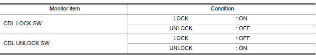
Check ("CDL LOCK SW ", "CDL UNLOCK SW") in "DATA MONITOR" mode for "POWER DOOR LOCK SYSTEM" with CONSULT.
POWER WINDOW MAIN SWITCH : Diagnosis Procedure
1. CHECK POWER WINDOW SWITCH OUTPUT SIGNAL
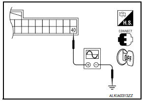
- Remove Intelligent Key, and close front door LH and RH.
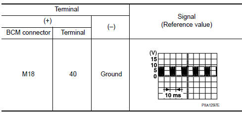
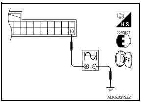
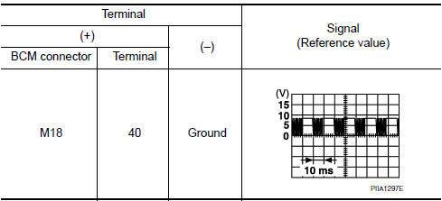
- Check signal between BCM connector M18 terminal 40 and ground with oscilloscope when door lock and unlock switch (key cylinder switch) is turned to "LOCK" or "UNLOCK".
- Check that signals which are shown in the figure below can be detected during 10 seconds just after door lock and unlock switch (key cylinder switch) is turned to "LOCK" or "UNLOCK".
2. CHECK POWER WINDOW SERIAL LINK CIRCUIT
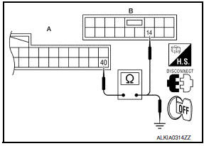
- Turn ignition switch OFF.
- Disconnect BCM connector M18 and main power window and door lock/unlock switch connector D7.
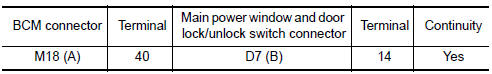
- Check continuity between BCM connector M18 (A) terminal 40 and main power window and door lock/unlock switch connector D7 (B) terminal 14.
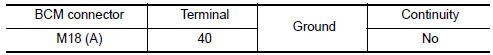
- Check continuity between BCM connector M18 (A) terminal 40 and ground.
POWER WINDOW MAIN SWITCH : Special Repair Requirement
1. PERFORM INITIALIZATION PROCEDURE
Perform initialization procedure.
2. CHECK ANTI-PINCH OPERATION
Check anti-pinch operation.
FRONT POWER WINDOW SWITCH
FRONT POWER WINDOW SWITCH : Description
- Main power window and door lock/unlock switch, power window and door lock/unlock switch RH and BCM communicate via the power window serial link
- The keyless power window down signal is transmitted from BCM to main power window and door lock/ unlock switch and power window and door lock/unlock switch RH.
- The following signals are transmitted from main power window and door lock/unlock switch to power window and door lock/unlock switch RH:
- Front door window RH operation
- Power window control by key cylinder switch
- Power window lock switch
- Retained accessory power operation
FRONT POWER WINDOW SWITCH : Diagnosis Procedure
1. CHECK POWER WINDOW AND DOOR LOCK/UNLOCK SWITCH RH
- Remove Intelligent Key, and close the front door LH and RH.
- Check signal between BCM connector M18 terminal 40 and ground with oscilloscope when door lock and unlock switch (key cylinder switch) is turned to "LOCK" or "UNLOCK".
- Check that signals which are shown in the figure below can be detected during 10 seconds just after door lock and unlock switch (key cylinder switch) is turned to "LOCK" or "UNLOCK".
2. CHECK POWER WINDOW SERIAL LINK CIRCUIT
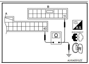
- Turn ignition switch OFF.
- Disconnect BCM connector M18 and power window and door lock/unlock switch RH connector.
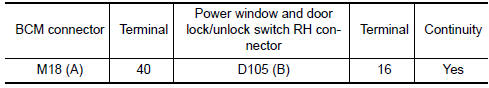
- Check continuity between BCM connector M18 (A) terminal 40 and power window and door lock/unlock switch RH connector D105 (B) terminal 16.
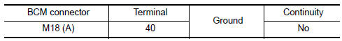
- Check continuity between BCM connector M18 (A) terminal 40 and ground.
FRONT POWER WINDOW SWITCH : Special Repair Requirement
1. PERFORM INITIALIZATION PROCEDURE
Perform initialization procedure.
2. CHECK ANTI-PINCH OPERATION
Check anti-pinch operation
 Door key cylinder switch
Description
The main power window and door lock/unlock switch detects condition of the
door key cylinder switch and
transmits to BCM as the LOCK or UNLOCK signal.
Component Function Check
1.CHE ...
 Power window lock switch
Component Function Check
1. CHECK POWER WINDOW LOCK
Activate the power window lock switch and verify that the front power window
RH, rear power window LH and
rear power window RH are inoperative ...
Other materials:
ABS branch line circuit
Diagnosis Procedure
1.CHECK CONNECTOR
Turn the ignition switch OFF.
Disconnect the battery cable from the negative terminal.
Check the terminals and connectors of the ABS actuator and
electric unit (control unit) for damage, bend
and loose connection (unit side and connector side).
...
Turn signal and hazard warning lamp system
Wiring Diagram
...
Climate controlled seat blower motor
Description
Sends airflow to the seat cushion and seatback.
Component Function Check
1.CHECK CLIMATE CONTROLLED SEAT BLOWER MOTOR FUNCTION
Turn the climate controlled seat switch to the H (Heat) LO, MED, and HI
positions and the C (Cool) LO, MED,
and HI positions. Check that the climate cont ...
Nissan Maxima Owners Manual
- Illustrated table of contents
- Safety-Seats, seat belts and supplemental restraint system
- Instruments and controls
- Pre-driving checks and adjustments
- Monitor, climate, audio, phone and voice recognition systems
- Starting and driving
- In case of emergency
- Appearance and care
- Do-it-yourself
- Maintenance and schedules
- Technical and consumer information
Nissan Maxima Service and Repair Manual

0.0076