
Nissan Maxima Service and Repair Manual: Microphone signal circuit
Description
Voice signals are transmitted from the microphone to the Bluetooth control unit using the microphone signal circuits.
Diagnosis Procedure
1.CHECK HARNESS BETWEEN BLUETOOTH CONTROL UNIT AND MICROPHONE
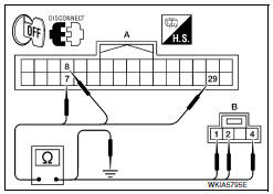
- Turn ignition switch OFF.
- Disconnect Bluetooth control unit connector and microphone connector.
- Check continuity between Bluetooth control unit harness connector B131 (A) and microphone harness connector R7 (B).
- Check continuity between Bluetooth control unit harness connector B131 (A) and ground.
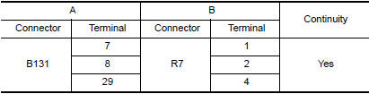
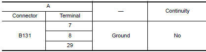
2.CHECK MICROPHONE POWER SUPPLY
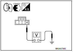
- Connect Bluetooth control unit connector and microphone connector.
- Turn ignition switch ON.
- Check voltage between microphone harness connector R7 terminal 4 and ground.

3.CHECK MICROPHONE SIGNAL
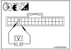
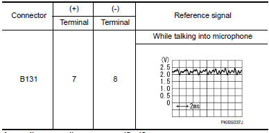
Check signal between Bluetooth control unit harness connector B131 terminals 7 and 8.
 Sound signal circuit
SATELLITE RADIO TUNER
SATELLITE RADIO TUNER : Description
Left and right channel audio signals are supplied from the satellite radio
tuner to the AV control unit through the sound signal circuits. ...

Other materials:
Power supply and ground circuit
BCM
BCM : Diagnosis Proce
1. CHECK FUSE AND FUSIBLE LINK
Check if the following BCM fuses or fusible link are blow
2. CHECK POWER SUPPLY CIRCUIT
Turn ignition switch OFF.
Disconnect BCM.
Check voltage between BCM harness connector and ground.
3. CHECK GROUND CIRCUIT
Check con ...
U1000 CAN comm circuit
Description
CAN (Controller Area Network) is a serial communication
line for real time applications. It is an on-vehicle multiplex
communication line with high data communication speed and excellent error
detection ability. Modern
vehicle is equipped with many electronic control unit, and e ...
STRG branch line circuit
Diagnosis Procedure
1.CHECK CONNECTOR
Turn the ignition switch OFF.
Disconnect the battery cable from the negative terminal.
Check the terminals and connectors of the steering angle sensor
for damage, bend and loose connection
(unit side and connector side).
2.CHECK HARNESS FOR OPE ...
Nissan Maxima Owners Manual
- Illustrated table of contents
- Safety-Seats, seat belts and supplemental restraint system
- Instruments and controls
- Pre-driving checks and adjustments
- Monitor, climate, audio, phone and voice recognition systems
- Starting and driving
- In case of emergency
- Appearance and care
- Do-it-yourself
- Maintenance and schedules
- Technical and consumer information
Nissan Maxima Service and Repair Manual

0.01