
Nissan Maxima Service and Repair Manual: Preparation
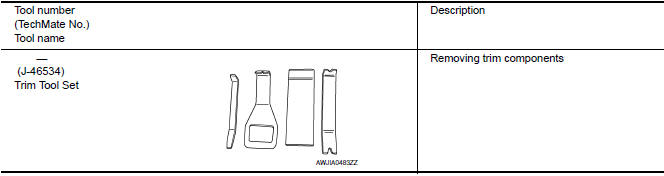
Special Service Tool
The actual shapes of the tools may differ from those illustrated here.
 Precaution
Precaution for Supplemental Restraint System (SRS) "AIR BAG" and "SEAT
BELT
PRE-TENSIONER"
The Supplemental Restraint System such as "AIR BAG" and "SEAT BELT PRE-TENSIONER",
...
 Periodic maintenance
PRE-INSPECTION FOR DIAGNOSTIC
Basic Inspection
BASIC INSPECTION
1.INSPECTION START
Check the service history.
Check the following parts.
Fuse/circuit breaker blown.
Poor connection, o ...
Other materials:
Rear combination lamp
Exploded View
Slide clip
Grommets
Rear combination lamp
Removal and Installation
REAR COMBINATION LAMP
Removal
Remove the trunk side finisher. Refer to INT-36, "Removal and
Installation".
Remove the rear combination lamp nuts.
Pull the rear combination lamp toward th ...
Basic inspection
DIAGNOSIS AND REPAIR WORKFLOW
Work Flow (With EXP-800 NI or GR8-1200 NI)
CHARGING SYSTEM DIAGNOSIS WITH EXP-800 NI OR GR8-1200 NI
To test the charging system, use the following special service tools:
EXP-800 NI Battery and electrical diagnostic analyzer
GR8-1200 NI Multitasking battery and ...
P1740 select solenoid
Description
The lock-up select solenoid valve controls
lock-up clutch pressure or forward clutch pressure (reverse brake
pressure).
When controlling lock-up clutch, the valve is
turned OFF. When controlling forward clutch, it is turned ON.
DTC Logic
DTC DET ...
Nissan Maxima Owners Manual
- Illustrated table of contents
- Safety-Seats, seat belts and supplemental restraint system
- Instruments and controls
- Pre-driving checks and adjustments
- Monitor, climate, audio, phone and voice recognition systems
- Starting and driving
- In case of emergency
- Appearance and care
- Do-it-yourself
- Maintenance and schedules
- Technical and consumer information
Nissan Maxima Service and Repair Manual

0.0107