Nissan Maxima Service and Repair Manual: Power seat for driver side
Wiring Diagram - Without Automatic Drive Positioner
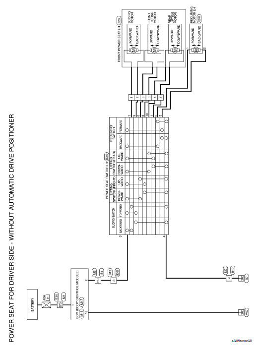
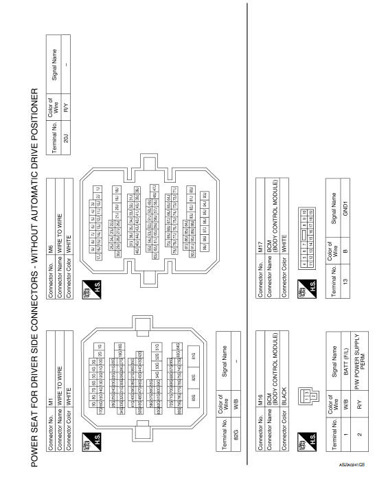
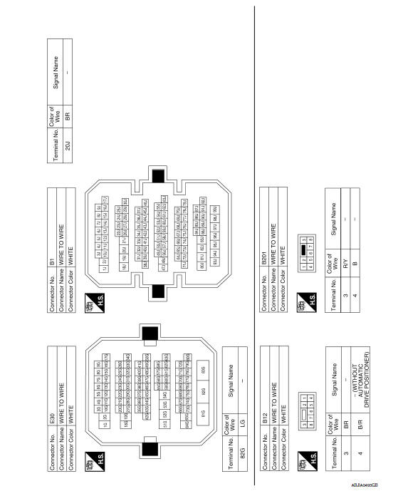
 Wiring diagram
...
 Power seat for passenger side
Wiring Diagram
...
Other materials:
Brake fluid
For additional information on brake fluid specification,
refer to "Recommended fluids/lubricants
and capacities" in the "Technical and consumer
information" section of this manual.
WARNING
Use only new fluid from a sealed container.
Old, inferior or contaminated
fluid may damage the ...
Map lights
To turn the map lights on, push the switches. To
turn them off, push the switches again.
CAUTION
Do not use for extended periods of time
with the engine stopped. This could result
in a discharged battery.
Personal lights
To turn the rear personal lights on, push the
switch. To turn the ...
Center speaker
Description
The audio unit sends audio signals to the BOSE speaker amp. The BOSE speaker
amp. amplifies the audio signals before sending them to the center speaker
using the audio signal circuits.
Diagnosis Procedure
1.CONNECTOR CHECK
Check the audio unit, BOSE speaker amp. and speaker conne ...
Nissan Maxima Owners Manual
- Illustrated table of contents
- Safety-Seats, seat belts and supplemental restraint system
- Instruments and controls
- Pre-driving checks and adjustments
- Monitor, climate, audio, phone and voice recognition systems
- Starting and driving
- In case of emergency
- Appearance and care
- Do-it-yourself
- Maintenance and schedules
- Technical and consumer information
Nissan Maxima Service and Repair Manual

0.006