Nissan Maxima Service and Repair Manual: Homelink universal transceiver
Description
Homelink universal transceiver can store and transmit a maximum of 3 radio signals.
Allows operation of garage doors, gates, home and office lighting, entry door locks and security system, etc.
Homelink universal transceiver power supply uses vehicle battery, which enables it to maintain every program in case battery is discharged or removed.
Component Function Check
1. CHECK FUNCTION
Check that system receiver (garage door opener, etc. ) operates with original hand-held transmitter
2. CHECK ILLUMINATE
- Turn ignition switch "OFF".
- Press each of the transmitter buttons and watch for the red light to illuminate with each button.
3. CHECK TRANSMITTER
Check transmitter with Tool*.
*:For details, refer to Technical Service Bulletin.
Diagnosis Procedure
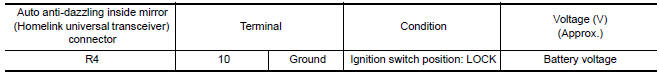
1. CHECK POWER SUPPLY
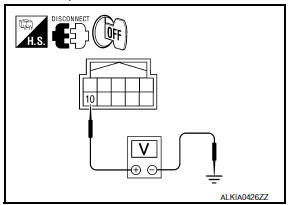
- Disconnect auto anti-dazzling inside mirror (homelink universal transceiver) connector.
- Check voltage between auto anti-dazzling inside mirror (homelink universal transceiver) harness connector and ground.
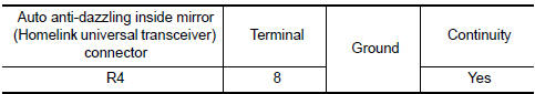
2. CHECK GROUND CIRCUIT
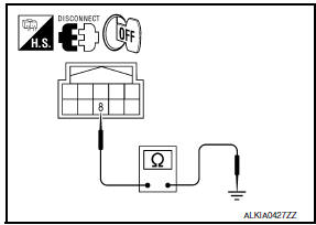
Check continuity between auto anti-dazzling inside mirror (homelink universal transceiver) harness connector and ground.
 Hazard function
Description
Perform answer-back for each operation with number of blinks.
Component Function Check
1. CHECK FUNCTION
Check hazard warning lamp ("FLASHER") in Active Test.
Diagnosis Procedure
1 ...
 ECU diagnosis information
BCM (BODY CONTROL MODULE)
Reference Value
NOTE:
The Signal Tech II Tool (J-50190) can be used to perform the following
functions. Refer to the Signal Tech II
User Guide for additional informat ...
Other materials:
U121D AV control unit
DTC Logic
Diagnosis Procedure
1.CHECK PLAYBACK OF A DISK (CD)
U121E AV CONTROL UNIT
DTC Logic
Diagnosis Procedure
1.CHECK PLAYBACK OF A DISK (CD)
U1225 AV CONTROL UNIT
DTC Logic
DTC DETECTION LOGIC
...
Trouble diagnosis
Condition of Error Detection
DTC (e.g. U1000 and U1001) of CAN communication is indicated on SELF-DIAG
RESULTS on CONSULT if a
CAN communication signal is not transmitted or received between units for 2
seconds or more.
CAN COMMUNICATION SYSTEM ERROR
CAN communication line open (CAN-H, ...
Blower unit
BLOWER UNIT
BLOWER UNIT : Removal and Installation
COMPONENTS
Heater and cooling unit
Blower unit Front
REMOVAL
Remove the heater and cooling unit assembly. Refer to HA-47,
"HEATER & COOLING UNIT ASSEMBLY : Removal and Installation".
Disconnect the harness connector from ...
Nissan Maxima Owners Manual
- Illustrated table of contents
- Safety-Seats, seat belts and supplemental restraint system
- Instruments and controls
- Pre-driving checks and adjustments
- Monitor, climate, audio, phone and voice recognition systems
- Starting and driving
- In case of emergency
- Appearance and care
- Do-it-yourself
- Maintenance and schedules
- Technical and consumer information
Nissan Maxima Service and Repair Manual

0.0056