Nissan Maxima Service and Repair Manual: Back-up lamp
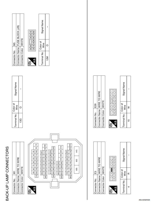
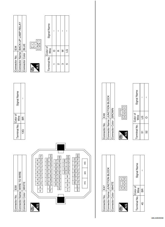
Wiring Diagram
 Stop lamp
Wiring Diagram
...

Other materials:
Intake Valve Timing Control
Exploded View
Intake valve timing control solenoid valve cover gasket (LH)
Intake valve timing control solenoid valve cover gasket (RH)
Intake valve timing control solenoid valve cover (RH) (bank 1)
Intake valve timing control solenoid valve (RH)
Intake valve timing control solenoid va ...
Steering wheel
Inspection
INSTALLATION CONDITION
Check installation conditions of steering gear assembly, front
suspension assembly, axle and steering column assembly.
Check if movement exists when steering wheel is moved up and down,
to the left and right and to the axial direction.
Check steering ...
On board diagnostic (OBD) system
Diagnosis Description
DESCRIPTION
The CVT system has two self-diagnostic systems.
The first is the emission-related on board diagnostic system (OBD-II) performed
by the TCM in combination
with the ECM. A malfunction is indicated by the MIL (Malfunction Indicator Lamp)
and is stored as a D ...
Nissan Maxima Owners Manual
- Illustrated table of contents
- Safety-Seats, seat belts and supplemental restraint system
- Instruments and controls
- Pre-driving checks and adjustments
- Monitor, climate, audio, phone and voice recognition systems
- Starting and driving
- In case of emergency
- Appearance and care
- Do-it-yourself
- Maintenance and schedules
- Technical and consumer information
Nissan Maxima Service and Repair Manual

0.0059