Nissan Maxima Service and Repair Manual: Preparation
Special Service Tool
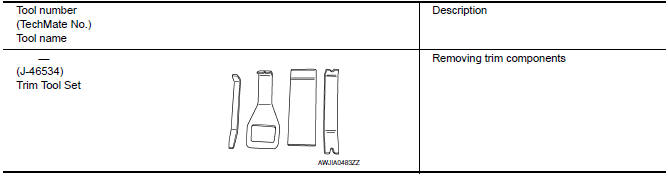
The actual shapes of the tools may differ from those illustrated here.
 Precaution
Precaution for Supplemental Restraint System (SRS) "AIR BAG" and
"SEAT BELT PRE-TENSIONER"
The Supplemental Restraint System such as "AIR BAG" and "SEAT BELT
PRE-TENSIONER", used along with a fro ...

Other materials:
Door switch
Description
Detects door open/close condition.
Component Function Check
1.CHECK FUNCTION
With CONSULT
Check door switches DOOR SW-DR, DOOR SW-AS in Data Monitor mode with CONSULT.
Diagnosis Procedure
1.CHECK DOOR SWITCH INPUT SIGNAL
Turn ignition switch OFF.
Check signal between B ...
General maintenance
FOR USA AND CANADA
FOR USA AND CANADA : Explanation of General Maintenance
General maintenance includes those items which should be checked during the
normal day-to-day operation
of the vehicle. They are essential if the vehicle is to continue operating
properly. The owners can perform
che ...
Diagnosis system (BCM)
COMMON ITEM
CONSULT Function (BCM - COMMON ITEM)
APPLICATION ITEM
CONSULT performs the following functions via CAN communication with BCM.
SYSTEM APPLICATION
BCM can perform the following functions.
RETAINED PWR
CONSULT Function (BCM - RETAINED PWR)
DATA MONITOR
...
Nissan Maxima Owners Manual
- Illustrated table of contents
- Safety-Seats, seat belts and supplemental restraint system
- Instruments and controls
- Pre-driving checks and adjustments
- Monitor, climate, audio, phone and voice recognition systems
- Starting and driving
- In case of emergency
- Appearance and care
- Do-it-yourself
- Maintenance and schedules
- Technical and consumer information
Nissan Maxima Service and Repair Manual

0.0049