Nissan Maxima Service and Repair Manual: Front wiper auto stop signal circuit
Component Function Check
1. CHECK FRONT WIPER (AUTO STOP) OPERATION
CONSULT DATA MONITOR
- Select "WIP AUTO STOP" of IPDM E/R DATA MONITOR item.
- Operate the front wiper.
- With the front wiper operation, check the monitor status.

Diagnosis Procedure
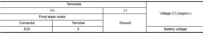
1. CHECK IPDM E/R OUTPUT VOLTAGE
- Turn the ignition switch OFF.
- Disconnect front wiper motor.
- Turn the ignition switch ON.
- Check voltage between front wiper motor harness connector and ground.
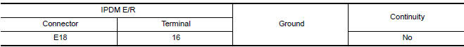
2. CHECK FRONT WIPER MOTOR (AUTO STOP) CIRCUIT CONTINUITY
- Turn the ignition switch OFF.
- Disconnect IPDM E/R connector E18.
- Check continuity between IPDM E/R harness connector and front wiper motor harness connector.
- Check continuity between IPDM E/R harness connector and ground.

 Front wiper motor hi circuit
Component Function Check
1. CHECK FRONT WIPER HI OPERATION
IPDM E/R AUTO ACTIVE TEST
Start IPDM E/R auto active test. Refer to PCS-11, "Diagnosis
Description".
Check that the front wiper op ...
 Front wiper motor ground circuit
Diagnosis Procedure
1.CHECK FRONT WIPER MOTOR (GND) OPEN CIRCUIT
Turn the ignition switch OFF.
Disconnect front wiper motor.
Check continuity between front wiper motor harness connector
...
Other materials:
Service data and specifications (SDS)
Oil Pressure
Regulator Valve
Oil Pump
Oil Capacity
...
Combination switch reading system
System Diagram
System Description
OUTLINE
BCM reads the status of the combination switch (light, turn
signal, wiper and washer) and recognizes the status of each switch.
BCM has a combination of 5 output terminals (OUTPUT 1 - 5) and 5
input terminals (INPUT 1 - 5) and reads a maximum ...
Precaution
PRECAUTIONS
Precaution for Supplemental Restraint System (SRS) "AIR BAG" and "SEAT
BELT
PRE-TENSIONER"
The Supplemental Restraint System such as "AIR BAG" and "SEAT BELT
PRE-TENSIONER", used along
with a front seat belt, helps to reduce the risk or severity of injury to t ...
Nissan Maxima Owners Manual
- Illustrated table of contents
- Safety-Seats, seat belts and supplemental restraint system
- Instruments and controls
- Pre-driving checks and adjustments
- Monitor, climate, audio, phone and voice recognition systems
- Starting and driving
- In case of emergency
- Appearance and care
- Do-it-yourself
- Maintenance and schedules
- Technical and consumer information
Nissan Maxima Service and Repair Manual

0.0087