Nissan Maxima Service and Repair Manual: Combination switch system symptoms
SYMPTOM DIAGNOSIS
COMBINATION SWITCH SYSTEM SYMPTOMS
Symptom Table
- Perform the data monitor of CONSULT to check for any malfunctioning item.
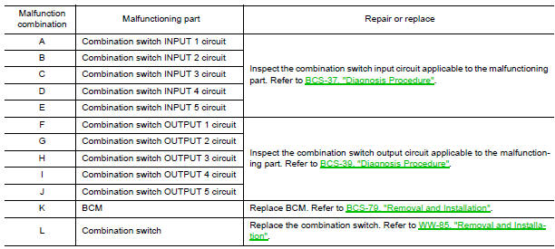
- Check the malfunction combinations
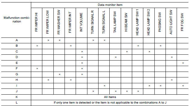
- Identify the malfunctioning part from the agreed combination and repair or replace the part.
 Wiring diagram
BCM (BODY CONTROL MODULE)
Wiring Diagram
...
 Precautions
PRECAUTION
Precaution for Supplemental Restraint System (SRS) "AIR BAG" and
"SEAT BELT PRE-TENSIONER "
The Supplemental Restraint System such as "AIR BAG" and "S ...
Other materials:
BCM (body control module)
Reference Value
NOTE:
The Signal Tech II Tool (J-50190) can be used
to perform the following functions. Refer to the Signal Tech II
User Guide for additional information.
Activate and display TPMS
transmitter IDs
Display tire pressure reported by
the TPMS transmitter
...
Audio unit
Reference Value
TERMINAL LAYOUT
PHYSICAL VALUES
...
Air Cleaner And Air Duct
Removal and Installation
Air duct hose and resonator assembly
Front air duct
Air cleaner case (lower)
Grommets
Air cleaner case mounting bracket
Bracket
Air cleaner filter
Air cleaner case (upper)
Mass air flow sensor
To electric throttle control
actuator
...
Nissan Maxima Owners Manual
- Illustrated table of contents
- Safety-Seats, seat belts and supplemental restraint system
- Instruments and controls
- Pre-driving checks and adjustments
- Monitor, climate, audio, phone and voice recognition systems
- Starting and driving
- In case of emergency
- Appearance and care
- Do-it-yourself
- Maintenance and schedules
- Technical and consumer information
Nissan Maxima Service and Repair Manual

0.0055