Nissan Maxima Service and Repair Manual: Diagnosis and repair workflow
Work Flow
OVERALL SEQUENCE
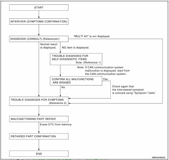
DETAILED FLOW
1.CHECK SYMPTOM
Check the malfunction symptoms by performing the following items.
- Interview the customer to obtain the malfunction information (conditions and environment when the malfunction occurred).
- Check the symptom.
2.SELF-DIAGNOSIS (CONSULT)
- Connect CONSULT and perform "SELF-DIAGNOSIS" for "MULTI AV". NOTE: Skip to step 4 of the diagnosis procedure if "MULTI AV" is not displayed.
- Check if any DTC No. is displayed in the self-diagnosis results.
3.CHECK SELF-DIAGNOSIS RESULTS (CONSULT)
- Check the DTC No. indicated in the self-diagnosis results.
- Perform the relevant diagnosis referring to the DTC No. list. Refer to AV-272, "DTC Index".
NOTE: Start with the diagnosis for the CAN communication system if "CAN COMM CIRCUIT [U1000] or CONTROL UNIT (CAN) [U1010]" is displayed.
4.PERFORM DIAGNOSIS BY SYMPTOM
5.REPAIR OR REPLACE MALFUNCTIONING PARTS
Repair or replace the identified malfunctioning parts.
NOTE: Erase the stored self-diagnosis results after repairing or replacing the relevant components if any DTC No. has been indicated in the self-diagnosis results.
6.CHECK AFTER REPAIR
- Perform self-diagnosis for "MULTI AV" with CONSULT after repairing or replacing the malfunctioning parts.
- Check if any DTC No. is displayed in the self-diagnosis results.
7.FINAL CHECK
Perform the operation check to confirm that the malfunction symptom is solved or that any other symptoms are present.
 Basic inspection
...
 Inspection and adjustment
REAR VIEW MONITOR POSSIBLE ROUTE LINE CENTER POSITION ADJUSTMENT
REAR VIEW MONITOR POSSIBLE ROUTE LINE CENTER POSITION ADJUSTMENT :
Description
Adjust the center position of the possible route lin ...
Other materials:
Unit disassembly and assembly
CENTER CONSOLE ASSEMBLY
Exploded View
Center console side finisher (LH)
Center console finisher
CVT finisher
Center console storage bin
Center console screw cover (LH)
Center console rear finisher
Center console screw cover (RH)
Center console
Center console lid assembly
...
Rear window glass
Exploded View
Rear window glass
Spacer
Rubber dam (if equipped)
Primer
Rear window molding
Adhesive
16 +2, -0 mm (0.63 +0.08, - 0 in)
7+ 2, - 0 mm (0.28 + 0.08, - 0 in)
12+ 2, - 0 mm (0.47 + 0.08, - 0 in)
Removal and Installation
REMOVAL
Partiall ...
P1801 vias control solenoid valve 2
Description
The VIAS control solenoid valve 2 cuts the intake manifold vacuum signal for
power valve 2 control. It
responds to ON/OFF signals from the ECM. When the solenoid is OFF, the vacuum
signal from the intake
manifold is cut. When the ECM sends an ON signal the coil pulls the plunger ...
Nissan Maxima Owners Manual
- Illustrated table of contents
- Safety-Seats, seat belts and supplemental restraint system
- Instruments and controls
- Pre-driving checks and adjustments
- Monitor, climate, audio, phone and voice recognition systems
- Starting and driving
- In case of emergency
- Appearance and care
- Do-it-yourself
- Maintenance and schedules
- Technical and consumer information
Nissan Maxima Service and Repair Manual

0.0076