Nissan Maxima Owners Manual: Operating range
The Intelligent Key functions can only be used when the Intelligent Key is within the specified operating range.
When the Intelligent Key battery is almost discharged or strong radio waves are present near the operating location, the Intelligent Key system's operating range becomes narrower and may not function properly.
If the Intelligent Key is within the operating range, it is possible for anyone, even someone who does not carry the Intelligent Key, to push the ignition switch to start the engine.
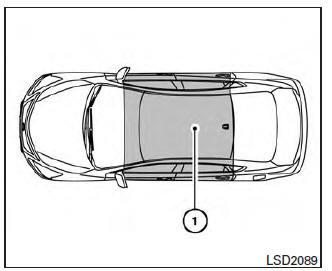
The operating range of the engine start function is inside of the vehicle 1 .
- The luggage area is not included in the operating range, but the Intelligent Key may function.
- If the Intelligent Key is placed on the instrument panel, inside the glove box, storage bin or door pocket, the Intelligent Key may not function.
- If the Intelligent Key is placed near the door or window outside the vehicle, the Intelligent Key may function.
 Push-Button Ignition Switch
WARNING
Do not operate the push-button ignition
switch while driving the vehicle except in
an emergency. (The engine will stop when
the ignition switch is pushed three consecutive
times in less t ...
 Push-button ignition switch positions
LOCK (Normal parking position)
The ignition switch can only be locked in this
position.
The ignition switch will be unlocked when it is
pushed to the ACC position while carrying the
Intelligent ...
Other materials:
NISSAN Vehicle Immobilizer System
The NISSAN Vehicle Immobilizer System will not
allow the engine to start without the use of the
registered key.
If the engine fails to start using a registered key
(for example, when interference is caused by
another registered key, an automated toll road
device or automatic payment device o ...
HomeLink Universal Transceiver
The HomeLink Universal Transceiver provides
a convenient way to consolidate the functions of
up to three individual hand-held transmitters into
one built-in device.
HomeLink Universal Transceiver:
Will operate most radio frequency devices
such as garage doors, gates, home and office
li ...
B2603 shift position status
Description
BCM confirms the shift position with the following 2
signals.
CVT selector lever
P/N position switch
DTC Logic
DTC DETECTION LOGIC
NOTE:
If DTC B2603 is displayed with DTC
U1000, first perform the trouble diagnosis for DTC U1000. Refer to
...
Nissan Maxima Owners Manual
- Illustrated table of contents
- Safety-Seats, seat belts and supplemental restraint system
- Instruments and controls
- Pre-driving checks and adjustments
- Monitor, climate, audio, phone and voice recognition systems
- Starting and driving
- In case of emergency
- Appearance and care
- Do-it-yourself
- Maintenance and schedules
- Technical and consumer information
Nissan Maxima Service and Repair Manual

0.0068