Nissan Maxima Service and Repair Manual: U1206 AV control unit
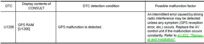
DTC Logic
Diagnosis Procedure
1.PERFORM THE SELF-DIAGNOSIS
- Delete the "self-diagnosis" results of "MULTI AV". Turn ignition switch OFF.
- Turn ignition switch ON. Perform the self-diagnosis again.
- Check that the DTC is detected again
 U1205 AV control unit
DTC Logic
Diagnosis Procedure
1.PERFORM THE SELF-DIAGNOSIS
Delete the "self-diagnosis" results of "MULTI AV". Turn ignition
switch OFF.
Turn ignition switch ON. Perform the self-diagnos ...
 U1207 AV control unit
DTC Logic
Diagnosis Procedure
1.PERFORM THE SELF-DIAGNOSIS
Delete the "self-diagnosis" results of "MULTI AV". Turn ignition
switch OFF.
Turn ignition switch ON. Perform the self-diagnos ...
Other materials:
Front coil spring and strut
Removal and Insallation
REMOVAL
Remove front wheel and tire using power tool. Refer to WT-60,
"Adjustment".
Remove the wheel sensor harness from the front coil spring and
strut. Refer to BRC-102, "Removal and Installation - Front Wheel Sensor".
Remove the brake hose lock plate.
Remo ...
System maintenance
The sensor A is located behind the lower grille
of the front bumper.
To keep the system operating properly, be sure to
observe the following:
Always keep the sensor area of the front
bumper clean.
Do not strike or damage the areas around
the sensor.
Do not cover or attach sticke ...
Wind deflector
Removal and Installation
REMOVAL
Open the glass lid.
Remove the side screw (A) to release the wind deflector side
arms (1). : Front
Disconnect and release the inner blind (1) slide clip from wind
deflector.
: Front
Remove the front screws (A), then remove wind deflector ...
Nissan Maxima Owners Manual
- Illustrated table of contents
- Safety-Seats, seat belts and supplemental restraint system
- Instruments and controls
- Pre-driving checks and adjustments
- Monitor, climate, audio, phone and voice recognition systems
- Starting and driving
- In case of emergency
- Appearance and care
- Do-it-yourself
- Maintenance and schedules
- Technical and consumer information
Nissan Maxima Service and Repair Manual

0.0063