Nissan Maxima Service and Repair Manual: AV control unit
Removal and Installation
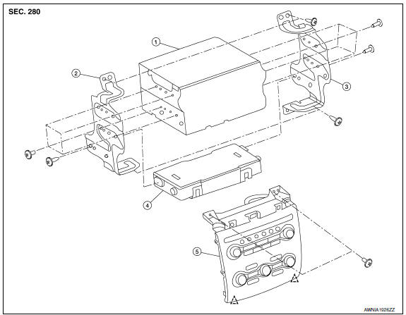
- AV control unit
- AV control unit bracket (LH)
- AV control unit bracket (RH)
- A/C auto amp.
- Cluster lid C (with A/C and AV switch
assembly attached)
 Clip
Clip
AV CONTROL UNIT
Removal
CAUTION: Before replacing AV control unit, perform "READ CONFIGURATION" to save current vehicle specification.
Refer to AV-337, "ADDITIONAL SERVICE WHEN REPLACING CONTROL UNIT : Special Repair Requirement".
- Disconnect the battery negative terminal. Refer to PG-67, "Removal and Installation (Battery)".
- Remove cluster lid D. Refer to IP-18, "Removal and Installation".
- Remove cluster lid C. Refer to IP-10, "Exploded View".
- Remove the AV control unit screws (A), then pull out the AV control unit (1), disconnect the AV control unit connectors and remove the AV control unit (1).
Installation
Installation is in the reverse order of removal.
CAUTION:
- When replacing AV control unit, perform "WRITE CONFIGURATION".
Refer to AV-337, "ADDITIONAL
SERVICE WHEN REPLACING CONTROL UNIT : Special Repair Requirement".
A/C AND AV SWITCH ASSEMBLY
Removal
- Remove cluster lid D. Refer to IP-18, "Removal and Installation".
- Remove cluster lid C. Refer to IP-10, "Exploded View".
- Remove the A/C and AV switch assembly screws (A), then pull out the A/C and AV switch assembly (1) from cluster lid C.
Installation
Installation is in the reverse order of removal.

 Multifunction switch
Removal and Installation
REMOVAL
Remove cluster lid D. Refer to IP-18, "Removal and Installation".
Remove the four multifunction switch screws (A) and the multifunction
switch ...
Other materials:
Climate controlled seat switch
Description
Provides inputs to the climate controlled seat control unit for climate
controlled seat operation.
Component Function Check
1.CHECK CLIMATE CONTROLLED SEAT SWITCH FUNCTION
Turn the climate controlled seat switch to the H (Heat) LO, MED, and HI
positions and the C (Cool) LO, MED, ...
Diagnosis system (BCM)
COMMON ITEM
COMMON ITEM : CONSULT Function (BCM - COMMON ITEM)
APPLICATION ITEM
CONSULT performs the following functions via CAN communication with BCM.
SYSTEM APPLICATION
BCM can perform the following functions.
BCM
BCM : CONSULT Function (BCM - BCM)
ECU IDENTIFICATION
The BCM part ...
B2581, B2582 intake sensor
Description
Intake Sensor
The intake sensor is located on the evaporator.
It converts air temperature after it passes through the evaporator
into a resistance value which is then input to the A/C auto amp.
Intake Sensor Circuit
DTC Logic
DTC DETECTION LOGIC
NOTE:
If DTC is di ...
Nissan Maxima Owners Manual
- Illustrated table of contents
- Safety-Seats, seat belts and supplemental restraint system
- Instruments and controls
- Pre-driving checks and adjustments
- Monitor, climate, audio, phone and voice recognition systems
- Starting and driving
- In case of emergency
- Appearance and care
- Do-it-yourself
- Maintenance and schedules
- Technical and consumer information
Nissan Maxima Service and Repair Manual

0.0061