Nissan Maxima Service and Repair Manual: Precaution
PRECAUTIONS
Precaution for Supplemental Restraint System (SRS) "AIR BAG" and "SEAT BELT PRE-TENSIONER"
The Supplemental Restraint System such as "AIR BAG" and "SEAT BELT PRE-TENSIONER", used along with a front seat belt, helps to reduce the risk or severity of injury to the driver and front passenger for certain types of collision. This system includes seat belt switch inputs and dual stage front air bag modules. The SRS system uses the seat belt switches to determine the front air bag deployment, and may only deploy one front air bag, depending on the severity of a collision and whether the front occupants are belted or unbelted.
Information necessary to service the system safely is included in the SR and SB section of this Service Manual.
WARNING:
- To avoid rendering the SRS inoperative, which could increase the risk of personal injury or death in the event of a collision which would result in air bag inflation, all maintenance must be performed by an authorized NISSAN/INFINITI dealer.
- Improper maintenance, including incorrect removal and installation of the SRS, can lead to personal injury caused by unintentional activation of the system. For removal of Spiral Cable and Air Bag Module, see the SR section.
- Do not use electrical test equipment on any circuit related to the SRS unless instructed to in this Service Manual. SRS wiring harnesses can be identified by yellow and/or orange harnesses or harness connectors.
PRECAUTIONS WHEN USING POWER TOOLS (AIR OR ELECTRIC) AND HAMMERS
WARNING:
- When working near the Airbag Diagnosis Sensor Unit or other Airbag System sensors with the Ignition ON or engine running, DO NOT use air or electric power tools or strike near the sensor(s) with a hammer. Heavy vibration could activate the sensor(s) and deploy the air bag(s), possibly causing serious injury.
- When using air or electric power tools or hammers, always switch the Ignition OFF, disconnect the battery, and wait at least 3 minutes before performing any service.
Precaution for Liquid Gasket
REMOVAL OF LIQUID GASKET
- After removing nuts and bolts, separate the mating surface using Tool and remove old liquid gasket.
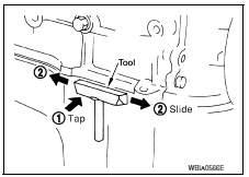
Tool number : KV10111100 (J-37228)
CAUTION: Be careful not to damage the mating surfaces.
- Tap (1) Tool to insert it, and then slide it (2) by tapping on the side as shown.
- In areas where Tool is difficult to use, use plastic hammer to lightly tap the parts, to remove it.
CAUTION: If for some unavoidable reason tool such as screwdriver is used, be careful not to damage the mating surfaces.
LIQUID GASKET APPLICATION PROCEDURE
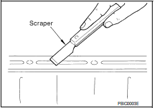
- Remove old liquid gasket adhering to the liquid gasket application surface and the mating surface using scraper.
- Remove liquid gasket completely from the groove of the liquid gasket application surface, bolts, and bolt holes.
- Thoroughly clean the mating surfaces and remove adhering moisture, grease and foreign materials.
- Attach liquid gasket tube to Tool.
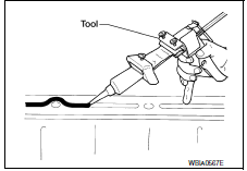
Tool number : WS39930000 ( - )
- Apply liquid gasket without breaks to the specified location with the specified dimensions.
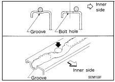
- If there is a groove for the liquid gasket application, apply liquid gasket to the groove.
- As for the bolt holes, normally apply liquid gasket inside the
holes. Occasionally, it should be applied outside the holes.
Make sure to read the text of Service Manual.
- Within five minutes of liquid gasket application, install the mating component.
- If liquid gasket protrudes, wipe it off immediately.
- Do not retighten nuts or bolts after the installation.
- After 30 minutes or more have passed from the installation, fill engine oil and engine coolant.
CAUTION: If there are more specific instructions in the procedures contained in this manual concerning liquid gasket application, observe them.

 Preparation
PREPARATION
Special Service Tool
The actual shapes of the tools may differ from those illustrated here
Commercial Service Tool
...
Other materials:
U1300 AV comm circuit
Description
U1300 is indicated when a communication signal malfunction occurs. U1300 is
indicated along with DTCs that identify components connected to the AV
control unit through communication lines. Determine the possible malfunction
cause from the table below.
SELF-DIAGNOSIS RESULTS DISPL ...
Changing engine oil
1. Park the vehicle on a level surface and apply
the parking brake.
2. Start the engine and let it idle until it reaches
operating temperature, then turn it off.
3. Remove the oil filler cap A by turning it
counterclockwise.
4. Remove clips B from the under-engine protector.
5 ...
DTC/circuit diagnosis
POWER SUPPLY AND GROUND CIRCUIT
COMBINATION METER
COMBINATION METER : Diagnosis Procedure
Regarding Wiring Diagram information, refer to MWI-87, "Wiring Diagram".
1.CHECK FUSES
Check for blown combination meter fuses.
2.POWER SUPPLY CIRCUIT CHECK
Disconnect combination meter connector.
...
Nissan Maxima Owners Manual
- Illustrated table of contents
- Safety-Seats, seat belts and supplemental restraint system
- Instruments and controls
- Pre-driving checks and adjustments
- Monitor, climate, audio, phone and voice recognition systems
- Starting and driving
- In case of emergency
- Appearance and care
- Do-it-yourself
- Maintenance and schedules
- Technical and consumer information
Nissan Maxima Service and Repair Manual

0.0057