
Nissan Maxima Service and Repair Manual: Preparation
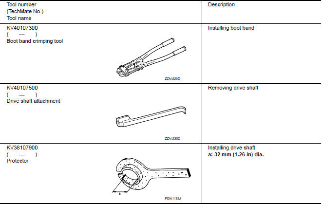
Special Service Tool
The actual shapes of the tools may differ from those illustrated here.
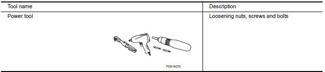
Commercial Service Tool
 Precaution
PRECAUTIONS
Precaution for Supplemental Restraint System (SRS) "AIR BAG" and
"SEAT BELT PRE-TENSIONER"
The Supplemental Restraint System such as "AIR BAG" and "SEAT BELT
PRE-TENSIONER", used alo ...
 Symptom diagnosis
NOISE, VIBRATION, AND HARSHNESS (NVH) TROUBLESHOOTING
NVH Troubleshooting Chart
Use chart below to help you find the cause of the symptom. If necessary,
repair or replace these parts.
× ...
Other materials:
P1212 TCS communication line
Description
This CAN communication line is used to control the smooth engine operation
during the TCS operation. Pulse
signals are exchanged between ECM and "ABS actuator and electric unit (control
unit)".
Be sure to erase the malfunction information such as DTC not only for "ABS
actuato ...
Conditions the remote start will not work
The remote start will not operate if any of the
following conditions are present:
"Remote Engine Start" is turned off in the
"Locking" section of the Vehicle Settings
menu.
The ignition switch is placed in the ON position.
The hood is not securely closed.
The hazard warning lights are ...
Power supply routing circuit
Wiring Diagram -Battery Power Supply -
Wiring Diagram -Accessory Power Supply -
Wiring Diagram -Ignition Power Supply -
Fuse
If fuse is blown, be sure to eliminate cause of malfunction before
installing new fuse.
U ...
Nissan Maxima Owners Manual
- Illustrated table of contents
- Safety-Seats, seat belts and supplemental restraint system
- Instruments and controls
- Pre-driving checks and adjustments
- Monitor, climate, audio, phone and voice recognition systems
- Starting and driving
- In case of emergency
- Appearance and care
- Do-it-yourself
- Maintenance and schedules
- Technical and consumer information
Nissan Maxima Service and Repair Manual

0.0092