Nissan Maxima Service and Repair Manual: Symptom diagnosis
NOISE, VIBRATION, AND HARSHNESS(NVH) TROUBLESHOOTING
NVH Troubleshooting Chart
Use the chart below to help you find the cause of the symptom. If necessary, repair or replace these parts.
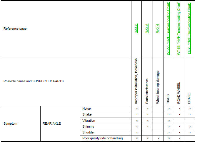
×: Applicable
 Preparation
Commercial Service Tool
...
 Periodic maintenance
WHEEL HUB
On-vehicle Service
Check axle and suspension parts for excessive play, wear or damage.
Shake each rear wheel to check for excessive play.
Inspection
Rear Wheel Bearing
...
Other materials:
Chassis & body maintenance
Abbreviations: I = Inspect and correct or replace as necessary, R =
Replace,
NOTE:
Maintenance items with " " should be performed more frequently according
to "Maintenance under severe driving conditions".
(1) If towing a trailer, using a camper or a car-top carrier or driving on ro ...
Front washer
WASHER TUBE
WASHER TUBE : Layout
Washer nozzle (LH)
Washer nozzle hose (LH)
Washer nozzle (RH)
Washer nozzle hose (RH)
Y-tube connector
Washer tank hose
Washer tank
Tube connectors
Clip
FRONT WASHER NOZZLE
FRONT WASHER NOZZLE : Removal and Installation
REMOVAL
...
Periodic maintenance
REAR SUSPENSION ASSEMBLY
On-vehicle Service
Check the suspension parts for excessive play, cracks, wear or damage.
Shake each rear wheel to check for excessive play.
Retighten all nuts and bolts to the specified torque.
Make sure that the cotter pin is installed.
Check the rear sho ...
Nissan Maxima Owners Manual
- Illustrated table of contents
- Safety-Seats, seat belts and supplemental restraint system
- Instruments and controls
- Pre-driving checks and adjustments
- Monitor, climate, audio, phone and voice recognition systems
- Starting and driving
- In case of emergency
- Appearance and care
- Do-it-yourself
- Maintenance and schedules
- Technical and consumer information
Nissan Maxima Service and Repair Manual

0.0058