Nissan Maxima Service and Repair Manual: Unit removal and installation
FRONT SUSPENSION ASSEMBLY
Exploded View
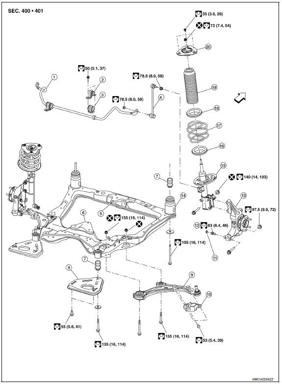
- Front stabilizer
- Stabilizer clamp
- Stabilizer bushing
- Stabilizer connecting rod
- Front mount bracket
- Rear mount bracket
- Member insulator
- Member pin stay
- Transverse link
- Steering stopper bracket
- Stopper bolt cap
- Steering stopper bolt
- Steering knuckle
- Front suspension member
- Front suspension strut
- Front spring lower rubber seat
- Front spring
- Strut mount bearing
- Bound bumper
- Strut mount insulator
Front
Removal and Installation
REMOVAL
- Engine, transmission and suspension member must be removed as an assembly. Refer to EM-103, "Removal and Installation".
- Once removed as an assembly, lift engine and transmission off suspension member using suitable tool.
INSTALLATION
Installation is in the reverse order of removal.
- After installation, perform final tightening of each part under unladen conditions with tires on ground. Refer to FSU-13, "Exploded View".
- Check wheel alignment. Refer to FSU-6, "Inspection and Adjustment".
 Steering knuckle
Removal and Installation
Steering knuckle
Splash guard
Wheel hub and bearing
Cotter pin
REMOVAL
Remove the front wheel hub and bearing. Refer to FAX-7, "Removal
and Installat ...
 Unit disassembly and assembly
FRONT COIL SPRING AND STRUT
Disassembly and Assembly
DISASSEMBLY
Install Tool (A) to the front coil spring and strut.
Tool number : ST35652000 ( - )
CAUTION: When installing Tool (A), wr ...
Other materials:
P0705 transmission range switch A
Description
The Transmission range switch is included in the control valve
assembly.
The Transmission range switch includes 4 transmission position
switches.
TCM judges the selector lever position by the Transmission range
switch signal.
DTC Logic
DTC DETECTI ...
Parking lamp circuit
Description
The IPDM E/R (intelligent power distribution module engine room) controls the
tail lamp relay based on inputs from the BCM over the CAN communication
lines. When the tail lamp relay is energized, power flows through fuses 46
and 47, located in the IPDM E/R. Power then flows to the ...
U1000 CAN comm circuit
Description
CAN (Controller Area Network) is a serial communication line for real time
application. It is an on-vehicle multiplex
communication line with high data communication speed and excellent error
detection ability. Many electronic
control units are equipped onto a vehicle and each c ...
Nissan Maxima Owners Manual
- Illustrated table of contents
- Safety-Seats, seat belts and supplemental restraint system
- Instruments and controls
- Pre-driving checks and adjustments
- Monitor, climate, audio, phone and voice recognition systems
- Starting and driving
- In case of emergency
- Appearance and care
- Do-it-yourself
- Maintenance and schedules
- Technical and consumer information
Nissan Maxima Service and Repair Manual

0.0077