Nissan Maxima Service and Repair Manual: Unit disassembly and assembly
FRONT COIL SPRING AND STRUT
Disassembly and Assembly
DISASSEMBLY
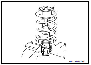
- Install Tool (A) to the front coil spring and strut.
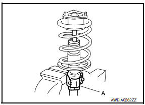
Tool number : ST35652000 ( - )
CAUTION: When installing Tool (A), wrap a shop cloth around the front coil spring and strut to protect the parts from damage.
- Secure Tool (A) in a vise.
- Slightly loosen the piston rod lock nut.
WARNING: Do not remove piston rod lock nut completely. If the piston rod lock nut is removed completely, the front spring can jump out and may cause serious damage or injury.
- Compress the front spring using a spring compressor (commercial service tool).
WARNING: Make sure that the pawls of the two spring compressors are firmly hooked on the front spring. The spring compressors must be tightened alternately so as not to tilt the front spring.
- Make sure the front spring is free between the strut mount bearing and
the front spring lower rubber seat.
Remove the piston rod lock nut.
- Remove the strut mount insulator, the bound bumper, and the strut mount bearing.
- Remove the bound bumper from the strut mount insulator.
- Gradually release the spring compressor (commercial service tool) and remove the front spring.
- Remove the front spring lower rubber seat.
ASSEMBLY
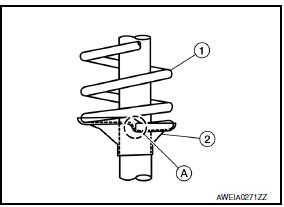
- Install the front spring lower rubber seat (2) to the front suspension strut.
- Compress the front spring (1) using a spring compressor (commercial service tool), and install the front spring to the front suspension strut.
WARNING: Make sure that the pawls of the two spring compressors are firmly hooked on the front spring. The spring compressors must be tightened alternately so as not to tilt the front spring.
CAUTION: Face the tube side of the coil spring downward. Align the front spring lower end (A) to the front spring lower rubber seat as shown.
- Install the bound bumper to the strut mount insulator.
CAUTION:
- Be sure to install the bound bumper to the strut mount insulator securely.
- When installing the bound bumper, use soapy water. Do not use machine oil or other lubricants.
- Install the strut mount bearing, the bound bumper, and the strut mount insulator to the strut. Temporarily install the piston rod lock nut.
CAUTION: Do not reuse the piston rod lock nut.
- Be sure tab (A) on strut mount insulator is positioned as shown.
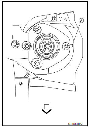
 : Front
- Be sure the front spring is properly set in the front spring lower
rubber seat. Gradually release the spring compressor (commercial service
tool).
CAUTION: Be sure the strut mount bearing is properly aligned to the strut mount insulator and to the front spring. - Tighten the piston rod lock nut to the specified torque.
- Remove Tool (A) from the vis
- Remove Tool (A) from the front coil spring and strut.
Tool number : ST35652000 ( - )
Inspection
INSPECTION AFTER DISASSEMBLY
Front Suspension Strut
- Check the front suspension strut for deformation, cracks, and damage. Replace if necessary.
- Check the piston rod for damage, uneven wear, and distortion. Replace if necessary.
- Check the welded and sealed areas for oil leakage. Replace if necessary.
Insulator and Rubber Parts
Check the strut mount insulator for cracks. Check the front spring lower rubber seat and the strut mount bearing for wear. Replace if necessary.
Front Spring
Check the front spring for cracks, wear, and damage. Replace if necessary.
 Unit removal and installation
FRONT SUSPENSION ASSEMBLY
Exploded View
Front stabilizer
Stabilizer clamp
Stabilizer bushing
Stabilizer connecting rod
Front mount bracket
Rear mount bracket
Member insulator
...
 Service data and specifications (SDS)
SERVICE DATA AND SPECIFICATIONS (SDS)
Wheel Alignment (Unladen*)
*: Fuel, engine coolant, and lubricants are full. Spare tire, jack, hand
tools, and mats are in designated positions.
Ball Joi ...
Other materials:
Exterior rear
Rear window defroster switch
High-mounted stop light
Interior trunk lid release. Trunk lid
Exterior trunk lid release/request button. Rearview camera
Rear sonar sensors (if so equipped)
Replacing bulbs
Fuel-filler door. Fuel recommendation
Child safety rear door locks
R ...
B2617 starter relay circuit
Description
Located in IPDM E/R, it runs the starter motor. The
starter relay is turned ON by the BCM when the ignition
switch is in START position. IPDM E/R transmits the starter relay ON signal to
BCM via CAN communication.
DTC Logic
DTC DETECTION LOGIC
NOTE:
If DTC B2617 is displ ...
Removal and installation
POWER SOCKET
Removal and Installation
POWER SOCKET
NOTE: If the tool does not fit because of
the location of the power socket, further disassembly may be required. Refer
to IP-14, "Removal and Installation".
Removal
Remove the fuse for the power socket.
Insert one end of the Tool (A) i ...
Nissan Maxima Owners Manual
- Illustrated table of contents
- Safety-Seats, seat belts and supplemental restraint system
- Instruments and controls
- Pre-driving checks and adjustments
- Monitor, climate, audio, phone and voice recognition systems
- Starting and driving
- In case of emergency
- Appearance and care
- Do-it-yourself
- Maintenance and schedules
- Technical and consumer information
Nissan Maxima Service and Repair Manual

0.0051