Nissan Maxima Service and Repair Manual: Shock absorber
Removal and Installation
REMOVAL

- Remove the rear wheel and tire using power tool. Refer to WT-60, "Adjustment".
- Set a jack under rear lower link to relieve the rear suspension spring tension.
- Remove the rear shock absorber lower nut and bolt with a power tool.
- Gradually lower the jack to disconnect the rear shock absorber from the rear axle housing.
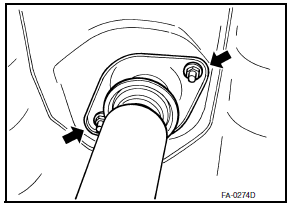
- Remove the rear shock absorber upper nuts (
 ) with a power tool, and then remove the rear shock absorber from
vehicle.
INSPECTION AFTER REMOVAL
- Check the rear shock absorber for deformation, cracks, and damage. Replace if necessary.
- Check welded and sealed areas for oil leakage. Replace if necessary.
INSTALLATION
- Installation is the reverse order of removal.
CAUTION: Do not reuse the rear shock absorber upper nuts.
- Perform the final tightening of the rear shock absorber lower nut and bolt under unladen condition with tires on level ground. Refer to RSU-15, "Exploded View".
- Check wheel alignment. Adjust as necessary. Refer to RSU-6, "Inspection and Adjustment".
- Adjust neutral position of steering angle sensor after checking the wheel alignment. Refer to BRC-6, "ADJUSTMENT OF STEERING ANGLE SENSOR NEUTRAL POSITION : Special Repair Requirement".
Disassembly and Assembly
DISASSEMBLY
CAUTION: Make sure the piston rod is not damaged when removing components from the rear shock absorber.
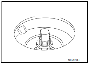
- Remove the rear shock absorber cap from the strut mount insulator.
- Wrap a shop cloth around the lower flanges of the rear shock absorber and secure the lower flanges in a vise. CAUTION: Do not set the cylindrical part of shock absorber in a vise.
- Secure the piston rod tip so that piston rod does not turn, and remove piston rod lock nut.
- Remove the strut mount insulator, the shock absorber mount seal, and the rear suspension bound bumper from the rear shock absorber.

INSPECTION AFTER DISASSEMBLY
Rear Suspension Bound Bumper and Shock Absorber Mount Seal
Check the rear suspension bound bumper and the shock absorber mount seal for cracks and damage.
Replace if necessary.
Rear Shock Absorber
- Check for uneven operation through a full stroke for both compression and extension.
- Check the rear shock absorber for deformation, cracks, or other damage. Replace if necessary.
- Check the piston rod for damage, uneven wear, and distortion. Replace if necessary.
- Check for oil leakage on the welded or gland packing portions.
ASSEMBLY
Installation is the reverse order of removal. For tightening torque, refer to RSU-15, "Exploded View".
CAUTION: Do not reuse the piston rod lock nut.
Make sure the piston rod is not damaged when attaching components to the rear shock absorber.
Disposal
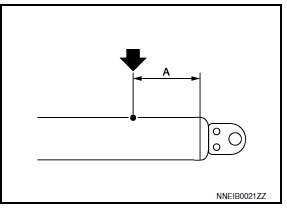
- Set the rear shock absorber horizontally with the piston rod fully extended.
- Drill 2 - 3 mm (0.08 - 0.12 in) hole at the position (
 ) from top as shown to release gas
gradually.
CAUTION:
- Wear eye protection (safety glasses).
- Wear gloves.
- Be careful with metal chips or oil blown out by the compressed gas.
NOTE:
- Drill vertically in this direction (
 ).
). - Directly to the outer tube avoiding brackets.
- The gas is clear, colorless, odorless, and harmless.

(A) : 20 - 30 mm (0.79 - 1.18 in)
- Position the drilled hole downward and drain oil by moving the piston rod several times.
CAUTION: Dispose of drained oil according to the law and local regulations.
 Rear lower link & coil spring
Removal and Installation
Removal
Remove the rear wheel and tire using power tool. Refer to WT-60,
"Adjustment".
Loosen the rear lower link adjusting bolt and nut at the rear
suspensio ...
 Front lower link
Removal and Installation
Removal
Remove the front lower link nut and bolt from the rear axle
housing using power tools.
Remove the adjusting bolt and nut from the rear suspension
member u ...
Other materials:
P0171, P0174 fuel injection system function
DTC Logic
DTC DETECTION LOGIC
With the Air/Fuel Mixture Ratio Self-Learning Control, the actual mixture
ratio can be brought closely to the
theoretical mixture ratio based on the mixture ratio feedback signal from A/F
sensor 1. The ECM calculates
the necessary compensation to correct the o ...
Exterior lighting system symptoms
Symptom Table
CAUTION: Perform the self-diagnosis with CONSULT
before the symptom diagnosis. Perform the trouble diagnosis if any DTC is
detected.
NORMAL OPERATING CONDITION
Description
AUTO LIGHT SYSTEM
The auto light system may not turn the headlamp ON/OFF immediately after
passing ...
Reclining motor
Description
The reclining motor is installed to the seatback assembly.
The reclining motor is activated with the driver seat control unit.
The seatback is reclined forward/backward by changing the rotation
direction of reclining motor.
Component Function Check
1. CHECK FUNCTION
Se ...
Nissan Maxima Owners Manual
- Illustrated table of contents
- Safety-Seats, seat belts and supplemental restraint system
- Instruments and controls
- Pre-driving checks and adjustments
- Monitor, climate, audio, phone and voice recognition systems
- Starting and driving
- In case of emergency
- Appearance and care
- Do-it-yourself
- Maintenance and schedules
- Technical and consumer information
Nissan Maxima Service and Repair Manual
0.0082
