Nissan Maxima Service and Repair Manual: Magnet clutch control system
System Diagram
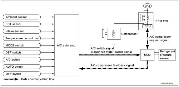
System Description
The A/C auto amp. controls A/C compressor operation by ambient temperature, intake air temperature and signal from ECM.
SYSTEM OPERATION
When the A/C switch, the AUTO switch, or the DEF switch is pressed, or when shifting mode position to D/F, the A/C auto amp. transmits the A/C switch signal and blower fan motor switch signal to the ECM, via CAN communication.
ECM judges whether the A/C compressor can be turned ON, based on each sensor status (refrigerant-pressure sensor signal, throttle angle, etc.). If the ECM judges that the A/C compressor can be turned ON, it sends A/C compressor request signal to the IPDM E/R, via CAN communication.
Upon receipt of A/C compressor request signal from the ECM, the IPDM E/R turns the A/C relay ON to operate the A/C compressor.
When sending A/C compressor request signal to the IPDM E/R via CAN communication line, the ECM simultaneously sends A/C compressor feedback signal to A/C auto amp. via CAN communication line.
The ECM sends A/C compressor feedback signal to A/C auto amp., then, uses input A/C compressor feedback signal to control air inlet.
A/C compressor Protection Control
The ECM makes the A/C relay turn OFF and stops the A/C compressor when pressure on the high-pressure side, detected by the refrigerant pressure sensor, is over approximately 3,119 kPa (31.8 kg/cm2, 452 psi), or below approximately 118 kPa (1.2 kg/cm2, 17 psi).
Low Temperature Protection Control
Turn the A/C relay to OFF and stop the A/C compressor by the signal from the A/C auto amp., according to the evaporator passing air temperature detected by the intake sensor and the ambient temperature detected by the ambient sensor
 Blower motor control system
System Diagram
System Description
Fan speed is automatically controlled by the temperature setting, ambient
temperature, in-vehicle temperature,
intake temperature, amount of sunload and air ...
 Can communication system
System Description
CAN (Controller Area Network) is a serial communication line for real time
application. It is an on-vehicle multiplex
communication line with high data communication speed and e ...
Other materials:
Parking brake switch signal circuit
Description
Transmits the parking brake switch signal to the
combination meter.
Component Function Check
1.COMBINATION METER INPUT SIGNAL
Select "METER/M&A" on CONSULT.
Monitor "PKB SW" of "DATA MONITOR" while
applying and releasing the parking brake.
> ...
Installing the spare tire
The spare tire is designed for emergency
use. For additional information, refer to
"Wheels and tires" in the "Do-it-yourself"
section of this manual.
1. Clean any mud or dirt from the surface between
the wheel and hub.
2. Carefully put the spare tire on and tighten
the wheel nuts finger ...
Vehicle security system
System Diagram
System Description
INPUT/OUTPUT SIGNAL CHART
OPERATION FLOW
SETTING THE VEHICLE SECURITY SYSTEM
Initial Condition
Ignition switch is in OFF position.
Disarmed Phase
When doors or trunk is open, the vehicle
security system is set in the dis ...
Nissan Maxima Owners Manual
- Illustrated table of contents
- Safety-Seats, seat belts and supplemental restraint system
- Instruments and controls
- Pre-driving checks and adjustments
- Monitor, climate, audio, phone and voice recognition systems
- Starting and driving
- In case of emergency
- Appearance and care
- Do-it-yourself
- Maintenance and schedules
- Technical and consumer information
Nissan Maxima Service and Repair Manual

0.0056