Nissan Maxima Service and Repair Manual: Insufficient cooling
Component Function Check
Symptom
- Insufficient cooling
- No cool air comes out. (Airflow volume is normal.)
INSPECTION FLOW
1. CONFIRM SYMPTOM BY PERFORMING OPERATION CHECK - TEMPERATURE DECREASE
- Press the AUTO switch.
- Turn temperature control switch (driver side) counterclockwise until 18C (60F) is displayed.
- Check for cold air at discharge air outlets.
2. CHECK FOR ANY SYMPTOMS
Perform a complete operational check and check for any symptoms
3. CHECK FOR SERVICE BULLETINS
Check for any service bulletins.
4. CHECK DRIVE BELTS
Check A/C compressor belt tension.
5.CHECK SETTING OF TEMPERATURE SETTING TRIMMER
Using CONSULT, check the setting of "TEMP SET CORRECT" on "WORK SUPPORT" of HVAC.
- Check that the temperature setting trimmer is set to "+ direction". NOTE: The control temperature can be set with the setting of the temperature setting trimmer.
- Set temperature control dial to "0".
6.CHECK WITH SELF-DIAGNOSIS FUNCTION OF CONSULT
- Using CONSULT, perform "SELF-DIAGNOSIS RESULTS" of HVAC.
- Check if any DTC No. is displayed in the trouble diagnosis results.
NOTE: If DTC is displayed along with DTC U1000 or U1010, first diagnose the DTC U1000 or U1010
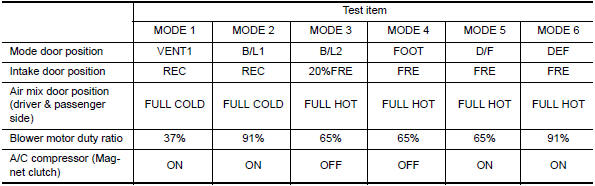
7.CHECK WITH ACTIVE TEST OF CONSULT
- Using CONSULT, perform "HVAC TEST""ACTIVE TEST" of HVAC to check each output device. Refer to HAC-129, "CONSULT Function". NOTE: Perform the ACTIVE TEST after starting the engine because the A/C compressor is operating.
- Refer to the table and check the outlet, inlet, airflow temperature, blower motor control signal, magnet clutch operation, and air mix ratio. Visually check each operating condition, by listening for noise, touching air outlets with a hand, etc.
8. CHECK AIR MIX DOOR MOTOR OPERATION
Check and verify air mix door mechanism for smooth operation.
9. CHECK COOLING FAN MOTOR OPERATION
Check and verify cooling fan motor for smooth operation.
10. CHECK RECOVERY/RECYCLING EQUIPMENT BEFORE USAGE
Check recovery/recycling equipment before connecting to vehicle. Verify there is no pressure in the recovery/ recycling equipment by checking the gauges. If pressure exists, recover refrigerant from equipment lines.
11. CHECK REFRIGERANT PURITY
- Connect recovery/recycling equipment to vehicle.
- Confirm refrigerant purity in supply tank using recovery/recycling and refrigerant indentifier.
12. CHECK REFRIGERANT PRESSURE
Check refrigerant pressure with manifold gauge connected
13. CHECK FOR EVAPORATOR FREEZE-UP
Start engine and run A/C. Check for evaporator freeze-up.
NOTE: Evaporator freeze up usually occurs at sustained highway speeds in hot, humid conditions with blend door at full-cold and blower on low speed, after 1-3 hours of continuous driving.
14. CHECK AIR DUCTS
Check ducts for air leaks.
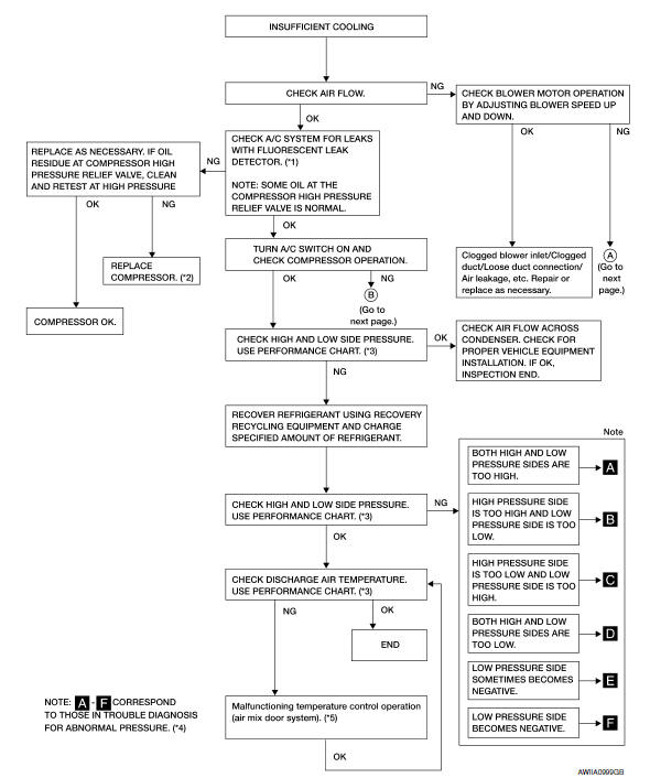
Diagnostic Work Flow
Performance Chart
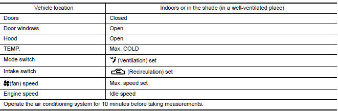
TEST CONDITION
Testing must be performed as follows
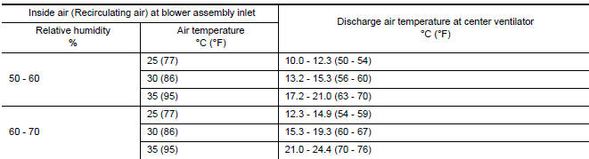
TEST READING
Recirculating-to-discharge Air Temperature Table
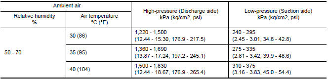
Ambient Air Temperature-to-operating Pressure Table

 Insufficient heating
Component Function Check
Symptom
Insufficient heating
No warm air comes out. (Airflow volume is normal.)
INSPECTION FLOW
1. CONFIRM SYMPTOM BY PERFORMING OPERATION CHECK - TEMPERATURE INCRE ...
Other materials:
Diagnosis system (BCM)
CONSULT Function (BCM - COMMON ITEM)
APPLICATION ITEM
CONSULT performs the following functions via CAN communication with BCM.
SYSTEM APPLICATION
BCM can perform the following functions.
CONSULT Function (BCM - AIR PRESSURE MONITOR)
NOTE: The Signal Tech II Tool (J-50190) can be used
to ...
Turn signal lamp circuit
Description
The BCM monitors inputs from the combination switch to determine when to
activate the turn signals. The BCM outputs voltage direction to the left and
right turn signals during turn signal operation or both during hazard warning
operation. The BCM sends a turn signal indicator requ ...
Parking, license plate and tail lamps are not turned on
Description
The parking, license plate and tail lamps do not turn ON in with any lighting
switch setting.
Diagnosis Procedure
1.COMBINATION SWITCH (LIGHTING AND TURN SIGNAL SWITCH) INSPECTION
Check the combination switch (lighting and turn signal switch).
2.CHECK TAIL LAMP RELAY REQUEST SIGNA ...
Nissan Maxima Owners Manual
- Illustrated table of contents
- Safety-Seats, seat belts and supplemental restraint system
- Instruments and controls
- Pre-driving checks and adjustments
- Monitor, climate, audio, phone and voice recognition systems
- Starting and driving
- In case of emergency
- Appearance and care
- Do-it-yourself
- Maintenance and schedules
- Technical and consumer information
Nissan Maxima Service and Repair Manual

0.0063