
Nissan Maxima Service and Repair Manual: Lumbar support system
Wiring Diagram
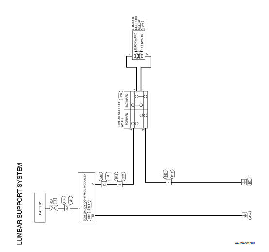
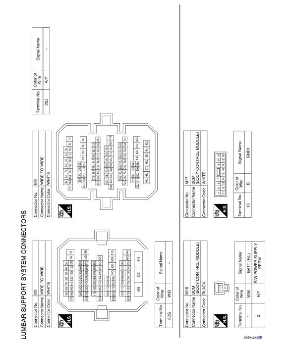
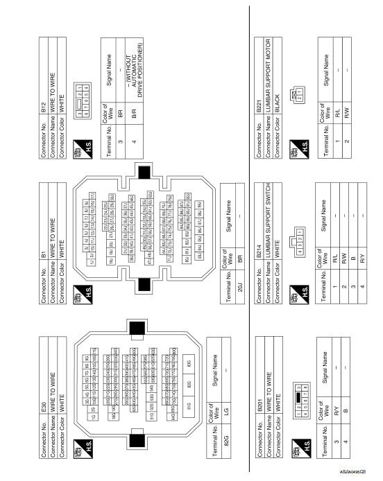
 Heated seat
Wiring Diagram
...
 Symptom diagnosis
SQUEAK AND RATTLE TROUBLE DIAGNOSES
Work Flow
CUSTOMER INTERVIEW
Interview the customer if possible, to determine the conditions that exist
when the noise occurs. Use the Diagnostic
Worksheet ...
Other materials:
Power generation voltage variable control system
System Diagram
System Description
Power generation variable voltage control system has been adopted. By varying
the voltage to the generator,
engine load due to power generation of the generator is reduced and fuel
consumption is decreased.
NOTE:
When any malfunction is detected in th ...
P0127 IAT sensor
Description
The intake air temperature sensor is built-into the mass air flow sensor
(1). The sensor detects intake air temperature and transmits a
signal to the ECM.
The temperature sensing unit uses a thermistor which is sensitive to
the change in temperature. Electrical resistance o ...
Refrigerant pressure sensor
Removal and Installation
REMOVAL
Discharge the refrigerant. Refer to HA-28, "Recycle Refrigerant".
Remove the core support upper cover.
Disconnect the harness connector from the refrigerant pressure
sensor.
Remove the refrigerant pressure sensor.
CAUTION:
Cap or wrap the ...
Nissan Maxima Owners Manual
- Illustrated table of contents
- Safety-Seats, seat belts and supplemental restraint system
- Instruments and controls
- Pre-driving checks and adjustments
- Monitor, climate, audio, phone and voice recognition systems
- Starting and driving
- In case of emergency
- Appearance and care
- Do-it-yourself
- Maintenance and schedules
- Technical and consumer information
Nissan Maxima Service and Repair Manual

0.011