Nissan Maxima Service and Repair Manual: Intelligent key warning buzzer
Description
Answers back and warns for an inappropriate operation.
Component Function Check
1. CHECK FUNCTION
With CONSULT
Check Intelligent Key warning buzzer OUTSIDE BUZZER in Active Test mode.
Diagnosis Procedure
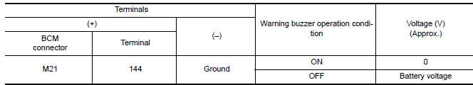
1. CHECK INTELLIGENT KEY WARNING BUZZER
Check voltage between BCM connector and ground.
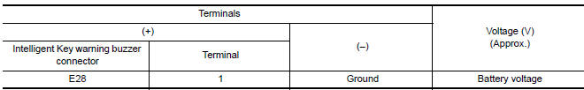
2. CHECK INTELLIGENT KEY WARNING BUZZER POWER SUPPLY CIRCUIT
- Turn ignition switch OFF.
- Disconnect Intelligent Key warning buzzer connector.
- Check voltage between Intelligent Key warning buzzer connector and ground.
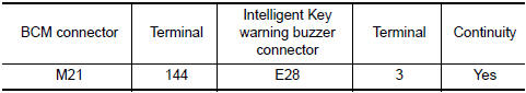
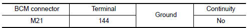
3. CHECK INTELLIGENT KEY WARNING BUZZER CIRCUIT
- Disconnect BCM connector.
- Check continuity between BCM connector and Intelligent Key warning buzzer connector.
- Check continuity between BCM connector and ground.
4. CHECK INTELLIGENT KEY WARNING BUZZER
5. CHECK INTERMITTENT INCIDENT
Component Inspection
1. CHECK INTELLIGENT KEY WARNING BUZZER
Connect battery power supply to Intelligent Key warning buzzer terminals 1 and 3, and check the operation.
1 (BAT+) - 3 (BAT-) : the buzzer sounds
 Trunk release solenoid
Description
Performs trunk lid open with signal from BCM.
Component Function Check
1. CHECK TRUNK LID OPENER CANCEL SWITCH
Check trunk lid opener cancel switch position.
2. CHECK FUNCTION
P ...
 Outside key antenna
Description
Detects whether Intelligent Key is outside the vehicle.
Integrated in front outside handle (driver side, passenger side) and installed
in rear bumper.
Component Function Check
NO ...
Other materials:
U121D AV control unit
DTC Logic
Diagnosis Pro
1.CHECK PLAYBACK OF A DISK (CD)
U121E AV CONTROL UNIT
DTC Logic
Diagnosis Procedure
1.CHECK PLAYBACK OF A DISK (CD)
U1225 AV CONTROL UNIT
DTC Logic
DTC DETECTION LOGIC
...
Blower motor control system
System Diagram
System Description
Fan speed is automatically controlled by the temperature setting, ambient
temperature, in-vehicle temperature,
intake temperature, amount of sunload and air mix door position.
By pressing the AUTO switch, the blower motor starts to gradually increase
a ...
Cleaning
If your windshield is not clear after using the
windshield-washer or if a wiper blade chatters
when running, wax or other material may be on
the blade or windshield.
Clean the outside of the windshield with a washer
solution or a mild detergent. Your windshield is
clean if beads do not form ...
Nissan Maxima Owners Manual
- Illustrated table of contents
- Safety-Seats, seat belts and supplemental restraint system
- Instruments and controls
- Pre-driving checks and adjustments
- Monitor, climate, audio, phone and voice recognition systems
- Starting and driving
- In case of emergency
- Appearance and care
- Do-it-yourself
- Maintenance and schedules
- Technical and consumer information
Nissan Maxima Service and Repair Manual

0.0057