Nissan Maxima Service and Repair Manual: Front combination lamp
Disassembly and Assembly
EXPLODED VIEW
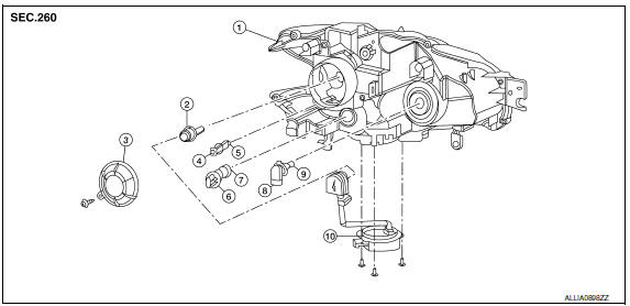
- Front combination lamp
- Xenon bulb
- Plastic cover
- Side marker lamp socket
- Side marker lamp bulb
- Front turn signal lamp socket
- Front turn signal lamp bulb
- Halogen bulb socket (high beam)
- Halogen bulb (high beam)
- HID control unit and xenon bulb socket
CAUTION: HID control unit and xenon bolb socket cannot be disassembled.
DISASSEMBLY
- Remove the screw from cover and rotate the plastic cover counterclockwise and unlock it.
- Rotate the xenon bulb socket counterclockwise and unlock it.
- Unlock the retaining spring and remove the xenon bulb.
- Remove the HID control unit installation screws.
- Remove the screw and disconnect the harness connector from the HID control unit.
- Remove the xenon bulb socket from front combination lamp.
- Rotate the halogen bulb socket counterclockwise and unlock it.
- Remove the bulb from halogen bulb socket.
- Rotate the front turn signal lamp socket counterclockwise and unlock it.
- Remove the bulb from front turn signal lamp socket.
- Rotate the front side marker lamp socket counterclockwise and unlock it.
- Remove the bulb from front side marker lamp socket.
ASSEMBLY
Assembly is in the reverse order of disassembly.
CAUTION:
- Install HID control unit securely.
- After installing the bulb, install the plastic cover and the bulb socket securely for watertightness.

 Rear combination lamp
Disassembly and Assembly
Rear combination lamp
Rear side marker lamp socket
Rear side marker lamp bulb
Rear turn signal lamp socket
Rear turn signal lamp bulb
Back-up lamp socket ...
Other materials:
Vehicle identification number (VIN) plate
The vehicle identification number (VIN) plate is
attached as shown. This number is the identification
for your vehicle and is used in the vehicle
registration.
Vehicle identification number (chassis number)
The vehicle identification number is located as
shown.
Engine serial number
...
System description
AUTOMATIC AIR CONDITIONER SYSTEM
WITH COLOR DISPLAY
WITH COLOR DISPLAY : Switches And Their Control F
WITH COLOR DISPLAY : Discharge Air Flow
WITH MONOCHROME DISPLAY
WITH MONOCHROME DISPLAY : Switches And Their Control Function
WITH MONOCHROME DISPLAY : Discharge Air Flow
...
P0507 ISC system
Description
The ECM controls the engine idle speed to a specified level via the fine
adjustment of the air, which is let into
the intake manifold, by operating the electric throttle control actuator. The
operating of the throttle valve is varied
to allow for optimum control of the engine id ...
Nissan Maxima Owners Manual
- Illustrated table of contents
- Safety-Seats, seat belts and supplemental restraint system
- Instruments and controls
- Pre-driving checks and adjustments
- Monitor, climate, audio, phone and voice recognition systems
- Starting and driving
- In case of emergency
- Appearance and care
- Do-it-yourself
- Maintenance and schedules
- Technical and consumer information
Nissan Maxima Service and Repair Manual

0.0062