Nissan Maxima Service and Repair Manual: Preparation
PREPARATION
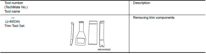
Special Service Tool
The actual shapes of the tools may differ from those illustrated here.
 Precaution
PRECAUTIONS
Precaution for Supplemental Restraint System (SRS) "AIR BAG" and
"SEAT BELT PRE-TENSIONER"
The Supplemental Restraint System such as "AIR BAG" and "SEAT BELT
PRE-TENSIONER", used alo ...

Other materials:
Heater & cooling unit assembly
Exploded View
Wiring harness
Mode door motor
Upper floor connecting duct (LH)
Air mix door motor (driver side)
Heater core pipes cover
Heater core
In-cabin microfilter
Filter cover
Blower motor
Intake door motor
Blower unit
Upper floor connecting duct (RH)
Air mi ...
Fuel Injector And Fuel Tube
Exploded View
Fuel feed hose
Quick connector cap
Fuel tube
O-ring
Fuel damper
Fuel damper cap
Clip
O-ring (black)
Fuel injector
O-ring (green)
Refer to INSTALLATION
Removal and Installation
REMOVAL
WARNING:
Put a "CAUTION: FLAMMABLE" sign in the worksho ...
P0447 evap canister vent control valve
Description
The EVAP canister vent control valve is located on the EVAP canister
and is used to seal the canister vent.
This solenoid valve responds to signals from the ECM. When the
ECM sends an ON signal, the coil in the solenoid valve is energized.
A plunger will then move to seal ...
Nissan Maxima Owners Manual
- Illustrated table of contents
- Safety-Seats, seat belts and supplemental restraint system
- Instruments and controls
- Pre-driving checks and adjustments
- Monitor, climate, audio, phone and voice recognition systems
- Starting and driving
- In case of emergency
- Appearance and care
- Do-it-yourself
- Maintenance and schedules
- Technical and consumer information
Nissan Maxima Service and Repair Manual

0.0078