
Nissan Maxima Service and Repair Manual: Service data and specifications (SDS)
Bulb Specifications
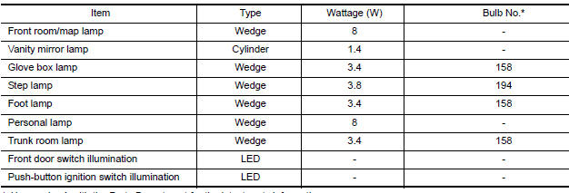
* Always check with the Parts Department for the latest parts information.
 Illumination
Removal and Installation
TRUNK ROOM LAMP
Removal
Release the tab (A), then swing open the lens.
: Front
Remove the bulb (3).
Release the tab (B), then pull trunk room lamp (2) away from ...
 Wiper & washer
...
Other materials:
Timing Chain
Exploded View
Timing chain tensioner (secondary)
Internal chain guide
Timing chain tensioner (secondary)
Camshaft sprocket (EXH)
Timing chain (secondary)
Timing chain (primary)
Camshaft sprocket (INT)
Camshaft sprocket (INT)
Timing chain (secondary)
Camshaft sprocket (E ...
Optical sensor
Exploded View
Optical sensor
LH front tweeter speaker grille
Optical sensor harness connector
LH front tweeter speaker
Instrument panel
Removal and Installation
CAUTION: Whenever a suitable tool is used,
always wrap a cloth around the end of the tool to protect components from ...
How to erase permanent DTC
Description
OUTLINE
When a DTC is stored in ECM
When a DTC is stored in ECM and MIL is ON, a permanent DTC is erased with MIL
shutoff if the same malfunction
is not detected after performing the driving pattern for MIL shutoff three times
in a raw.
*1: When the same malfunction is detect ...
Nissan Maxima Owners Manual
- Illustrated table of contents
- Safety-Seats, seat belts and supplemental restraint system
- Instruments and controls
- Pre-driving checks and adjustments
- Monitor, climate, audio, phone and voice recognition systems
- Starting and driving
- In case of emergency
- Appearance and care
- Do-it-yourself
- Maintenance and schedules
- Technical and consumer information
Nissan Maxima Service and Repair Manual

0.009