Nissan Maxima Service and Repair Manual: Can communication circuit
Diagnosis Procedure
1.CONNECTOR INSPECTION
- Turn the ignition switch OFF.
- Disconnect the battery cable from the negative terminal.
- Disconnect all the unit connectors on CAN communication system.
- Check terminals and connectors for damage, bend and loose connection.
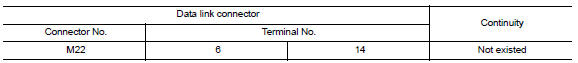
2.CHECK HARNESS CONTINUITY (SHORT CIRCUIT)
Check the continuity between the data link connector terminals.
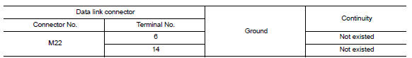
3.CHECK HARNESS CONTINUITY (SHORT CIRCUIT)
Check the continuity between the data link connector and the ground.
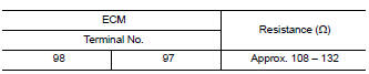
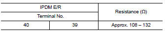
4.CHECK ECM AND IPDM E/R TERMINATION CIRCUIT
1. Remove the ECM and the IPDM E/R.
2. Check the resistance between the ECM terminals.
3. Check the resistance between the IPDM E/R terminals.
5.CHECK SYMPTOM
Connect all the connectors. Check if the symptoms described in the "Symptom (Results from interview with customer)" are reproduced.
Inspection result
Reproduced>>GO TO 6.
Non-reproduced>>Start the diagnosis again. Follow the trouble diagnosis procedure when past error is detected.
6.CHECK UNIT REPRODUCTION
Perform the reproduction test as per the following procedure for each unit.
- Turn the ignition switch OFF.
- Disconnect the battery cable from the negative terminal.
- Disconnect one of the unit connectors of CAN communication system.
NOTE: ECM and IPDM E/R have a termination circuit. Check other units first.
- Connect the battery cable to the negative terminal. Check if the
symptoms described in the "Symptom
(Results from interview with customer)" are reproduced.
NOTE: Although unit-related error symptoms occur, do not confuse them with other symptoms.
Inspection result Reproduced>>Connect the connector. Check other units as per the above procedure.
Non-reproduced>>Replace the unit whose connector was disconnected.
 IPDM-E branch line circuit
Diagnosis Procedure
1.CHECK CONNECTOR
Turn the ignition switch OFF.
Disconnect the battery cable from the negative terminal.
Check the terminals and connectors of the IPDM E/R for damage,
...

Other materials:
Exhaust gas (carbon monoxide)
WARNING
Do not breathe exhaust gases; they
contain colorless and odorless carbon
monoxide. Carbon monoxide is dangerous.
It can cause unconsciousness or
death.
If you suspect that exhaust fumes are
entering the vehicle, drive with all windows
fully open, and have the vehicle
in ...
Intake sensor
Removal and Installation
REMOVAL
Remove the evaporator (2). Refer to HA-48, "EVAPORATOR:
Removal and Installation".
Release the intake sensor clip (A), then remove the intake sensor
(1).
CAUTION:
Mark the mounting position of the intake sensor.
Do not damage the evapora ...
Basic inspection
DIAGNOSIS AND REPAIR WORKFLOW
Work Flow
OVERALL SEQUENCE
DETAILED FLOW
1.CONFIRM SYMPTOM
Confirm symptom or customer complaint.
2.CHECK SELF-DIAGNOSIS OPERATION OF COMBINATION METER
Perform self-diagnosis of combination meter. Refer to MWI-29, "Diagnosis
Description".
3.CHECK COMBINATION ...
Nissan Maxima Owners Manual
- Illustrated table of contents
- Safety-Seats, seat belts and supplemental restraint system
- Instruments and controls
- Pre-driving checks and adjustments
- Monitor, climate, audio, phone and voice recognition systems
- Starting and driving
- In case of emergency
- Appearance and care
- Do-it-yourself
- Maintenance and schedules
- Technical and consumer information
Nissan Maxima Service and Repair Manual

0.0053