Nissan Maxima Service and Repair Manual: ECM branch line circuit
Diagnosis Procedure
1.CHECK CONNECTOR
- Turn the ignition switch OFF.
- Disconnect the battery cable from the negative terminal.
- Check the following terminals and connectors for damage, bend and
loose connection (unit side and connector
side).
- Models without automatic drive positioner - ECM - Harness connector E30 - Harness connector M1 - Models with automatic drive positioner - ECM - Harness connector E29 - Harness connector B10
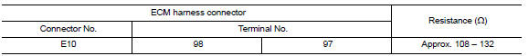
2.CHECK HARNESS FOR OPEN CIRCUIT
- Disconnect the connector of ECM.
- Check the resistance between the ECM harness connector terminals.
3.CHECK POWER SUPPLY AND GROUND CIRCUIT
Check the power supply and the ground circuit of the ECM. Refer to EC-157, "Diagnosis Procedure".
 Main line between A-bag and ABS circuit
Diagnosis Procedure
1.CHECK CONNECTOR
Turn the ignition switch OFF.
Disconnect the battery cable from the negative terminal.
Check the following terminals and connectors for damage, bend and ...
 BCM branch line circuit
Diagnosis Procedure
1.CHECK CONNECTOR
Turn the ignition switch OFF.
Disconnect the battery cable from the negative terminal.
Check the terminals and connectors of the BCM for damage, bend and ...
Other materials:
Power steering oil pump
Inspection
CAUTION: Make sure that belt tension is
normal before starting the following procedure.
Connect the Tool between oil pump discharge connector and
high-pressure hose. Bleed air from the hydraulic circuit while opening
the shut-off valve fully. Refer to ST-12, "Inspection".
...
DTC/circuit diagnosis
SUNSHADE
Component Parts Location
Rear sunshade unit B22 (View with the rear parcel shelf finisher
removed)
Rear sunshade switch M308
Reference Value
...
Push-Button Ignition Switch
WARNING
Do not operate the push-button ignition
switch while driving the vehicle except in
an emergency. (The engine will stop when
the ignition switch is pushed three consecutive
times in less than 1.5 seconds or
the ignition switch is pushed and held for
more than 2 seconds.) If the engine ...
Nissan Maxima Owners Manual
- Illustrated table of contents
- Safety-Seats, seat belts and supplemental restraint system
- Instruments and controls
- Pre-driving checks and adjustments
- Monitor, climate, audio, phone and voice recognition systems
- Starting and driving
- In case of emergency
- Appearance and care
- Do-it-yourself
- Maintenance and schedules
- Technical and consumer information
Nissan Maxima Service and Repair Manual

0.0058