Nissan Maxima Service and Repair Manual: ECU diagnosis information
IPDM E/R (INTELLIGENT POWER DISTRIBUTION MODULE ENGINE ROOM)
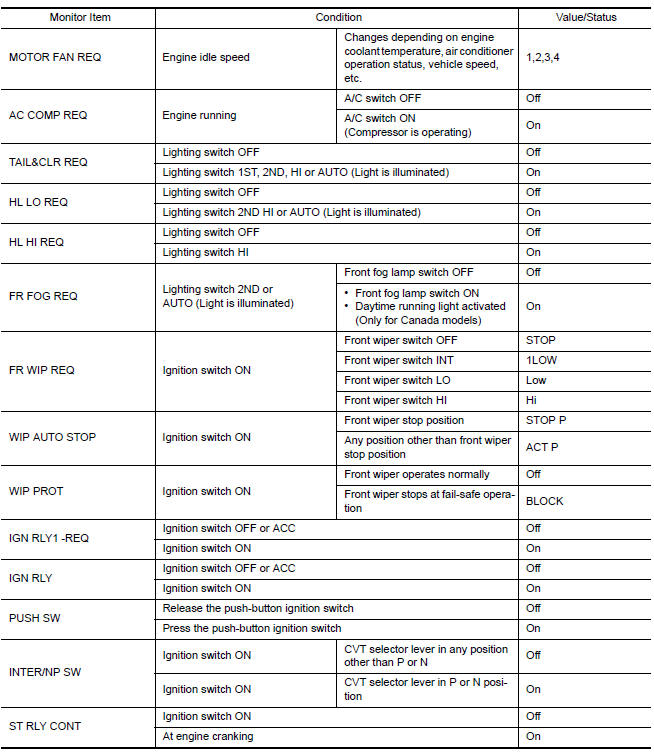
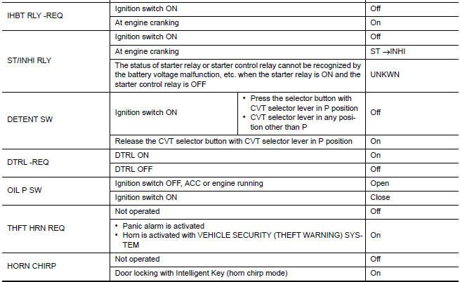
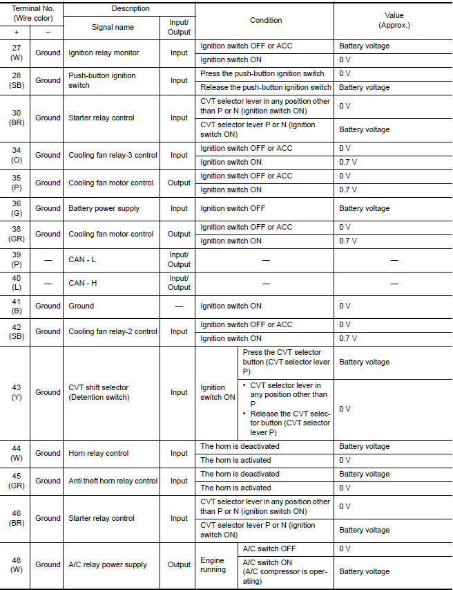
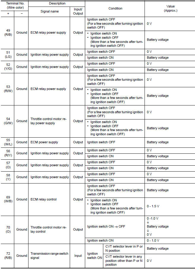
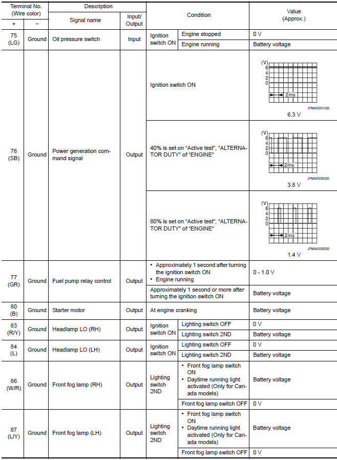
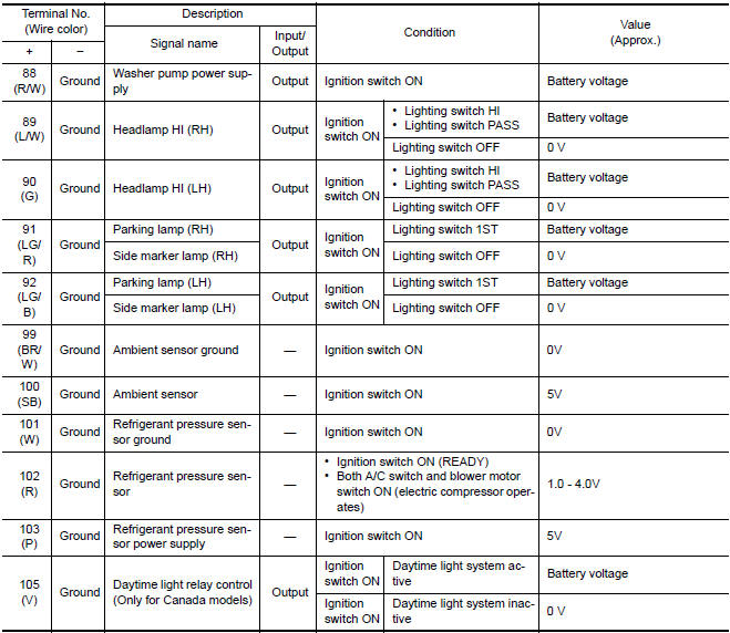
Reference Value
VALUES ON THE DIAGNOSIS TOOL
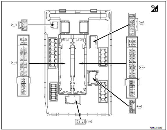
TERMINAL LAYOUT
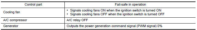
Fail Safe
CAN COMMUNICATION CONTROL
When CAN communication with ECM and BCM is impossible, IPDM E/R performs fail-safe control. After CAN communication recovers normally, it also returns to normal control.
If No CAN Communication Is Available With ECM
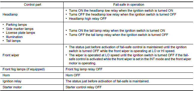
If No CAN Communication Is Available With BCM
IGNITION RELAY MALFUNCTION DETECTION FUNCTION
- IPDM E/R monitors the voltage at the contact circuit and excitation coil circuit of the ignition relay-1 inside it.
- IPDM E/R judges the ignition relay-1 error if the voltage differs between the contact circuit and the excitation coil circuit.
- If the ignition relay-1 cannot turn OFF due to contact seizure, it activates the tail lamp relay for 10 minutes to alert the user to the ignition relay-1 malfunction when the ignition switch is turned OFF.
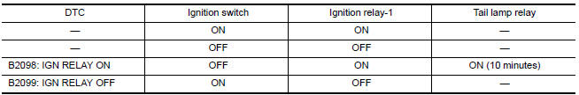
NOTE: The tail lamp turns OFF when the ignition switch is turned ON.
FRONT WIPER CONTROL
IPDM E/R detects front wiper stop position by a front wiper auto stop signal.
When a front wiper auto stop signal is in the conditions listed below, IPDM E/R stops power supply to wiper after repeating a front wiper 10 seconds activation and 20 seconds stop five times.
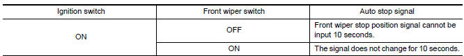
NOTE: This operation status can be confirmed on the IPDM E/R "Data Monitor" that displays "BLOCK" for the item "WIP PROT" while the wiper is stopped.
STARTER MOTOR PROTECTION FUNCTION
IPDM E/R turns OFF the starter control relay to protect the starter motor when the starter control relay remains active for 90 seconds.
DTC Index
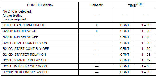
NOTE: The details of TIME display are as follows.
- CRNT: The malfunctions that are detected now
- 1 - 39: The number is indicated when it is normal at present and a malfunction was detected in the past. It increases like 0 → 1 → 2 ??* 38 → 39 after returning to the normal condition whenever IGN OFF → ON. It is fixed to 39 until the self-diagnosis results are erased if it is over 39. It returns to 0 when a malfunction is detected again in the process.
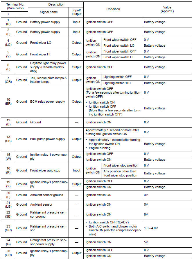
 Power supply and ground circuit
Diagnosis Procedure
1. CHECK FUSES AND FUSIBLE LINK
Check that the following IPDM E/R fuses or fusible link are not blown.
2. CHECK POWER SUPPLY CIRCUIT
Turn ignition switch OFF.
Disconne ...
 Wiring diagram
IPDM E/R (INTELLIGENT POWER DISTRIBUTION MODULE ENGINE
ROOM)
Wiring Diagram
...
Other materials:
Daytime running light system
System Diagram
System Description
The headlamp system for Canada vehicles is equipped with a daytime light
relay that activates the high beam headlamps at approximately half
illumination whenever the engine is running. If the parking brake is
depressed before the engine is started, the day ...
Front seat
DRIVER SIDE
DRIVER SIDE : Exploded View
Driver Seat - Without Climate Controlled Seats
Headrest
Headrest holder (free)
Headrest holder (locked)
Seatback board
Seatback board clip
Seat cushion inner finisher inside (RH)
Recline mechanism inner cover
Seat cushion outer finis ...
Optical sensor
Exploded View
Optical sensor
LH front tweeter speaker grille
Optical sensor harness connector
LH front tweeter speaker
Instrument panel
Removal and Installation
CAUTION: Whenever a suitable tool is used,
always wrap a cloth around the end of the tool to protect components from ...
Nissan Maxima Owners Manual
- Illustrated table of contents
- Safety-Seats, seat belts and supplemental restraint system
- Instruments and controls
- Pre-driving checks and adjustments
- Monitor, climate, audio, phone and voice recognition systems
- Starting and driving
- In case of emergency
- Appearance and care
- Do-it-yourself
- Maintenance and schedules
- Technical and consumer information
Nissan Maxima Service and Repair Manual

0.0062