Nissan Maxima Service and Repair Manual: Wiring diagram
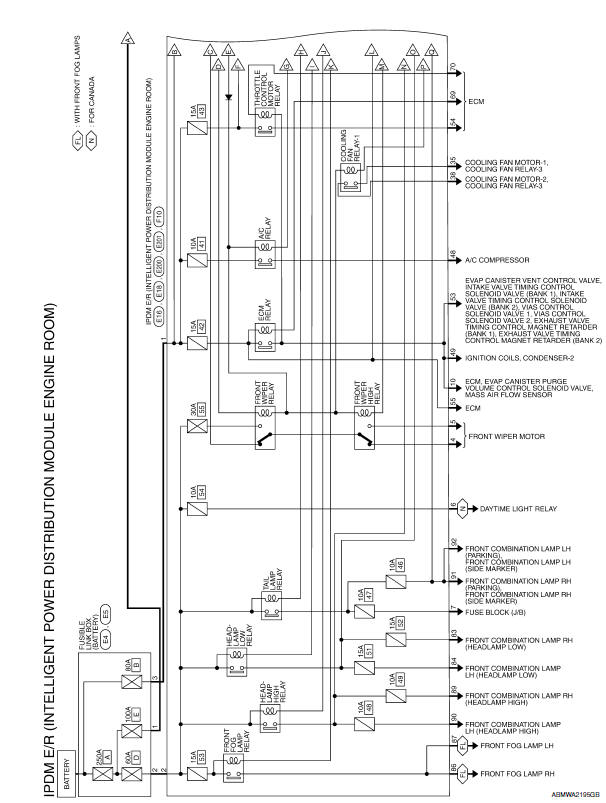
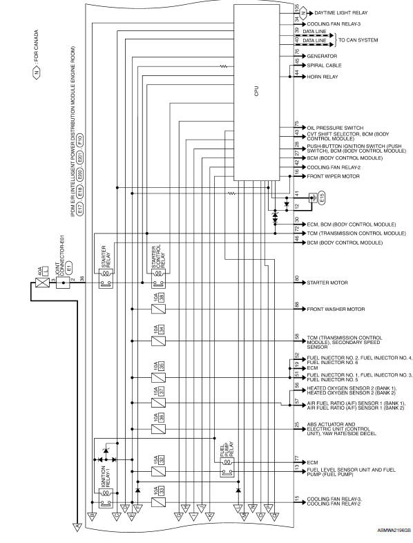
IPDM E/R (INTELLIGENT POWER DISTRIBUTION MODULE ENGINE ROOM)
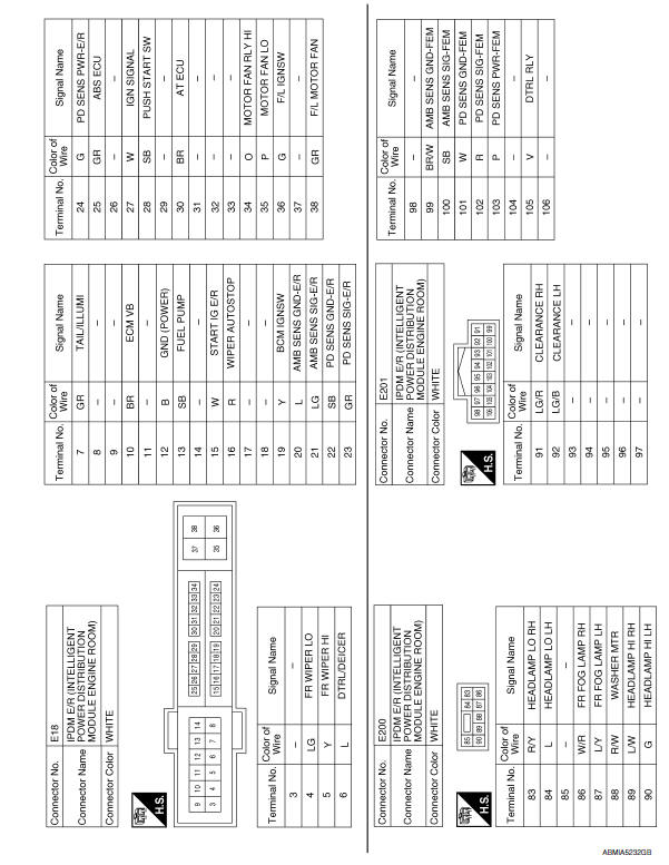
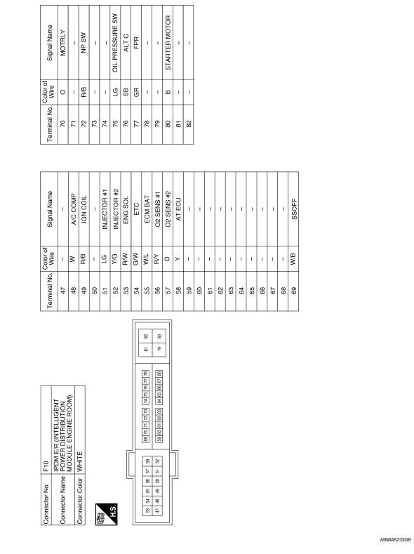
Wiring Diagram
 ECU diagnosis information
IPDM E/R (INTELLIGENT POWER DISTRIBUTION MODULE ENGINE
ROOM)
Reference Value
VALUES ON THE DIAGNOSIS TOOL
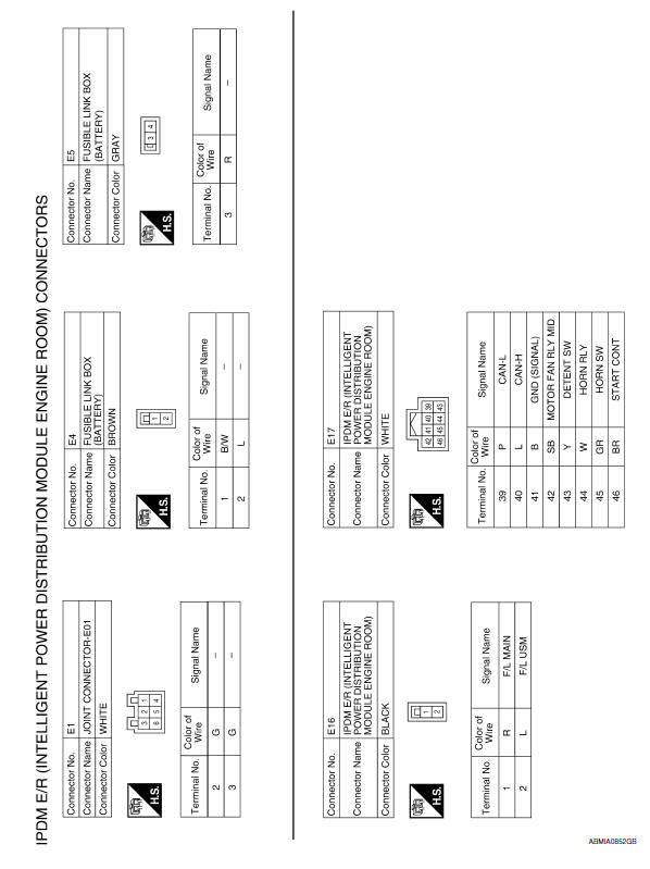
TERMINAL LAYOUT
Fail Safe
CAN COMMUNICATION CONTROL
Wh ...
 Precaution
Precaution for Supplemental Restraint System (SRS) "AIR BAG" and "SEAT
BELT
PRE-TENSIONER"
The Supplemental Restraint System such as "AIR BAG" and "SEAT BELT PRE-TENSIONER",
...
Other materials:
P0447 evap canister vent control valve
Description
The EVAP canister vent control valve is located on the EVAP canister
and is used to seal the canister vent.
This solenoid valve responds to signals from the ECM. When the
ECM sends an ON signal, the coil in the solenoid valve is energized.
A plunger will then move to seal ...
Oil Pan And Oil Strainer
Exploded View
Oil pan baffle
O-ring
Gasket
Oil pressure switch
Oil cooler gasket
Oil cooler
Oil cooler connection
Oil filter
Lower oil pan
Oil strainer
Rear plate cover
Crankshaft position sensor (POS)
O-ring
Upper oil pan
Removal and Installation (Lower O ...
ECU diagnosis information
BCM (BODY CONTROL MODULE)
Reference Value
NOTE: The Signal Tech II Tool (J-50190) can be used
to perform the following functions. Refer to the Signal Tech II User Guide
for additional information.
Activate and display TPMS transmitter IDs
Display tire pressure reported by the ...
Nissan Maxima Owners Manual
- Illustrated table of contents
- Safety-Seats, seat belts and supplemental restraint system
- Instruments and controls
- Pre-driving checks and adjustments
- Monitor, climate, audio, phone and voice recognition systems
- Starting and driving
- In case of emergency
- Appearance and care
- Do-it-yourself
- Maintenance and schedules
- Technical and consumer information
Nissan Maxima Service and Repair Manual

0.006