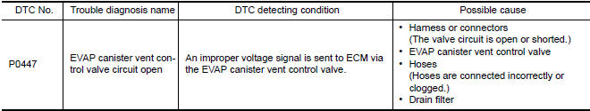
Nissan Maxima Service and Repair Manual: P0447 evap canister vent control valve
Description
The EVAP canister vent control valve is located on the EVAP canister and is used to seal the canister vent.
This solenoid valve responds to signals from the ECM. When the ECM sends an ON signal, the coil in the solenoid valve is energized.
A plunger will then move to seal the canister vent. The ability to seal the vent is necessary for the on board diagnosis of other evaporative emission control system components.
This solenoid valve is used only for diagnosis, and usually remains opened.
When the vent is closed, under normal purge conditions, the evaporative emission control system is depressurized and allows "EVAP Control System" diagnosis.
DTC Logic
DTC DETECTION LOGIC
DTC CONFIRMATION PROCEDURE
1.PRECONDITIONING
If DTC Confirmation Procedure has been previously conducted, always perform the following before conducting the next test.
- Turn ignition switch OFF and wait at least 10 seconds.
- Turn ignition switch ON.
- Turn ignition switch OFF and wait at least 10 seconds.
TESTING CONDITION: Before performing the following procedure, confirm battery voltage is more than 11 V at idle.
2.PERFORM DTC CONFIRMATION PROCEDURE
- Start engine and wait at least 8 seconds.
- Check 1st trip DTC.
Diagnosis Procedure
1.INSPECTION START
2.CHECK EVAP CANISTER VENT CONTROL VALVE CIRCUIT
With CONSULT
- Turn ignition switch OFF and then ON.
- Select "VENT CONTROL/V" in "ACTIVE TEST" mode with CONSULT.
- Touch "ON/OFF" on CONSULT screen.
- Check for operating sound of the valve.
Clicking sound should be heard.
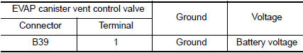
3.CHECK EVAP CANISTER VENT CONTROL VALVE POWER SUPPLY CIRCUIT
- Turn ignition switch OFF.
- Disconnect EVAP canister vent control valve harness connector.
- Turn ignition switch ON.
- Check the voltage between EVAP canister vent control valve harness connector and ground.
4.DETECT MALFUNCTIONING PART
Check the following.
- Harness connectors B10, E29
- Harness connectors E11, F2
- Harness for open or short between EVAP canister vent control valve and IPDM E/R
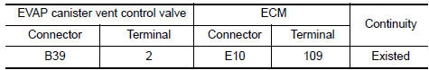
5.CHECK EVAP CANISTER VENT CONTROL VALVE OUTPUT SIGNAL CIRCUIT FOR OPEN AND SHORT
- Turn ignition switch OFF.
- Disconnect ECM harness connector.
- Check the continuity between ECM harness connector and EVAP
canister vent control valve harness connector.
Refer to Wiring Diagram.
- Also check harness for short to ground and short to power.
6.DETECT MALFUNCTIONING PART
Check the following.
- Harness connectors B10, E29
- Harness for open or short between EVAP canister vent control valve and ECM
7.CHECK RUBBER TUBE FOR CLOGGING
- Disconnect rubber tube connected to EVAP canister vent control valve.
- Check the rubber tube for clogging.
8.CHECK DRAIN FILTER
9.CHECK EVAP CANISTER VENT CONTROL VALVE
10.CHECK INTERMITTENT INCIDENT
Component Inspection
EVAP CANISTER VENT CONTROL VALVE
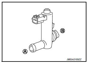
1.CHECK EVAP CANISTER VENT CONTROL VALVE-I
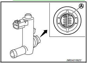
- Remove EVAP canister vent control valve from EVAP canister. Refer to FL-16, "Removal and Installation".
- Check portion (A) of EVAP canister vent control valve for rust.
2.CHECK EVAP CANISTER VENT CONTROL VALVE-II
With CONSULT
- Reconnect harness connectors disconnected.
- Turn ignition switch ON.
- Perform "VENT CONTROL/V" in "ACTIVE TEST" mode.
- Check air passage continuity and operation delay time.
Check that new O-ring is installed properly.
Operation takes less than 1 second.
Without CONSULT
- Disconnect EVAP canister vent control valve harness connector.
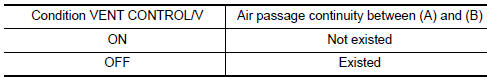
- Check air passage continuity and operation delay time under the
following conditions.
Check that new O-ring is installed properly.
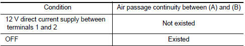
Operation takes less than 1 second.
3.CHECK EVAP CANISTER VENT CONTROL VALVE
With CONSULT
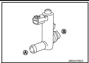
- Clean the air passage [portion (A) to (B)] of EVAP canister vent control valve using an air blower.
- Perform "VENT CONTROL/V" in "ACTIVE TEST" mode.
- Check air passage continuity and operation delay time.
Check that new O-ring is installed properly.
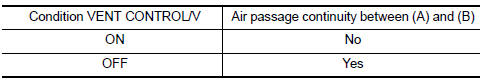
Operation takes less than 1 second.
Without CONSULT
- Clean the air passage [portion (A) to (B)] of EVAP canister vent control valve using an air blower.
- Check air passage continuity and operation delay time under the following conditions.
Check that new O-ring is installed properly.
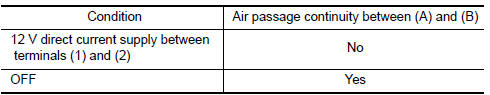
Operation takes less than 1 second.
DRAIN FILTER
- Check visually for insect nests in the drain filter air inlet.
- Check visually for cracks or flaws in the appearance.
- Check visually for cracks or flaws in the hose.
- Blow air into port A and check that it flows freely out of port B.
- Block port B.
- Blow air into port A and check that there is no leakage.
- If NG, replace drain filter.
 P0444, P0445 evap canister purge volume control solenoid
valve
P0444, P0445 evap canister purge volume control solenoid
valve
Description
The EVAP canister purge volume control solenoid valve is used to
control the flow rate of fuel vapor from the EVAP canister. The EVAP
canister purge volume control solenoid valve ...
 P0448 evap canister vent control valve
Description
The EVAP canister vent control valve is located on the EVAP canister
and is used to seal the canister vent.
This solenoid valve responds to signals from the ECM. When the
ECM s ...
Other materials:
P1705 TP sensor
Description
The electric throttle control actuator consists of
throttle control motor, accelerator pedal position sensor, throttle
position sensor, etc. The actuator sends a signal to the ECM, and ECM sends the
signal to TCM via CAN
communication.
DTC Logic
DTC DETECTION LOGIC
DTC CONF ...
Dehumidified defrosting or defogging
1. Press the front
defroster button on.
2. Turn the temperature control dial to set the
maximum temperature to aid in defrosting or
defogging.
To quickly remove ice from the outside of the
windows, use the fan speed
control
buttons to set the fan speed to maximum.
As soon ...
Speedometer and odometer
This vehicle is equipped with a speedometer and
odometer. The speedometer is located on the
right side of the meter cluster. The odometer is
located within the vehicle information display.
Speedometer
The speedometer indicates vehicle speed.
Odometer/Twin trip odometer
The odometer and ...
Nissan Maxima Owners Manual
- Illustrated table of contents
- Safety-Seats, seat belts and supplemental restraint system
- Instruments and controls
- Pre-driving checks and adjustments
- Monitor, climate, audio, phone and voice recognition systems
- Starting and driving
- In case of emergency
- Appearance and care
- Do-it-yourself
- Maintenance and schedules
- Technical and consumer information
Nissan Maxima Service and Repair Manual

0.0062