Nissan Maxima Service and Repair Manual: Basic inspection
DIAGNOSIS AND REPAIR WORKFLOW
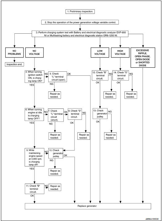
Work Flow (With EXP-800 NI or GR8-1200 NI)
CHARGING SYSTEM DIAGNOSIS WITH EXP-800 NI OR GR8-1200 NI
To test the charging system, use the following special service tools:
- EXP-800 NI Battery and electrical diagnostic analyzer
- GR8-1200 NI Multitasking battery and electrical diagnostic station
NOTE: Refer to the applicable Instruction Manual for proper charging system diagnosis procedures.
OVERALL SEQUENCE
DETAILED FLOW
NOTE: To ensure a complete and thorough diagnosis, the battery, starter and generator test segments must be done as a set from start to finish.
1.PRELIMINARY INSPECTION
Perform the preliminary inspection
2.STOP POWER GENERATION VOLTAGE VARIABLE CONTROL SYSTEM
Stop the operation of the power generation voltage variable control in either of the following procedures.
- After selecting "ENGINE" using CONSULT, set the DUTY value of "ALTERNATOR DUTY" to 0 % by selecting "ALTERNATOR DUTY" of "Active Test". Continue "Active Test" until the end of inspection. (When the DUTY value is 0 or 100 %, the normal power generation is performed according to the characteristic of the IC regulator of the generator.)
- Turn the ignition switch OFF, and disconnect the battery current sensor connector. [However, DTC (P1550- P1554) of the engine might remain. After finishing the inspection, connect the battery current sensor connector and erase the self diagnosis results history of the engine using CONSULT.]
3.DIAGNOSIS WITH EXP-800 NI OR GR8-1200 NI
Perform the charging system test using Multitasking battery and electrical diagnostic station GR8-1200 NI or Battery and electrical diagnostic analyzer EXP-800 NI. Refer to the applicable Instruction Manual for proper testing procedures.
4.INSPECTION WITH CHARGE WARNING LAMP (IGNITION SWITCH IS ON)
Turn the ignition switch ON.
5."L" TERMINAL CIRCUIT (OPEN) INSPECTION
Check "L" terminal circuit (open).
6.INSPECTION WITH CHARGE WARNING LAMP (IDLING)
Start the engine and run it at idle.
7."L" TERMINAL CIRCUIT (SHORT) INSPECTION
Check "L" terminal circuit (short).
8."S" TERMINAL CIRCUIT INSPECTION
Check "S" terminal circuit
9.INSPECTION WITH CHARGE WARNING LAMP (ENGINE AT 3,000 RPM)
Increase and maintain the engine speed at 3,000 rpm.
10.INSPECTION OF GENERATOR PULLEY
Check generator pulley.
11."B" TERMINAL CIRCUIT INSPECTION
Check "B" terminal circuit
12."B" TERMINAL CIRCUIT INSPECTION
Check "B" terminal circuit
13.INSPECTION OF GENERATOR PULLEY
Check generator pulley
14."S" TERMINAL CIRCUIT INSPECTION
Check "S" terminal circuit.
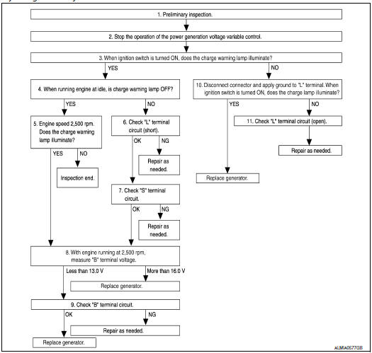
Work Flow (Without EXP-800 NI or GR8-1200 NI)
OVERALL SEQUENCE
Before performing a generator test, make sure that the battery is fully charged. A 30-volt voltmeter and suitable test probes are necessary for the test.
- Before starting, inspect the fusible link.
- Use fully charged battery
DETAILED FLOW
1.PRELIMINARY INSPECTION
Perform the preliminary inspection
2.STOP POWER GENERATION VOLTAGE VARIABLE CONTROL SYSTEM
Stop the operation of the power generation voltage variable control in either of the following procedures:
- After selecting "ENGINE" using CONSULT, set the DUTY value of "ALTERNATOR DUTY" to 0 % by selecting "ALTERNATOR DUTY" with "Active Test". Continue "Active Test" until the end of inspection. (When the DUTY value is 0 or 100 %, the normal power generation is performed according to the characteristic of the IC regulator of the generator.)
- Turn the ignition switch OFF, and disconnect the battery current sensor connector. [However, DTC (P1550 - P1554) of the engine might remain. After finishing the inspection, connect the battery current sensor connector and erase the self-diagnostic results history of the engine using CONSULT.]
3.INSPECTION WITH CHARGE WARNING LAMP (IGNITION SWITCH IS TURNED ON)
When ignition switch is turned ON.
4.INSPECTION WITH CHARGE WARNING LAMP (IDLING)
Start the engine and run it at idle
5.INSPECTION WITH CHARGE WARNING LAMP (ENGINE AT 2,500 RPM)
Increase and maintain the engine speed at 2,500 rpm.
6."L" TERMINAL CIRCUIT (SHORT) INSPECTION
Check terminal "L" circuit for (short).
7. "S" TERMINAL CIRCUIT INSPECTION
Check terminal "S" circuit.
8.MEASURE "B" TERMINAL VOLTAGE
Start engine. With engine running at 2,500 rpm, measure "B" terminal voltage.
9."B" TERMINAL CIRCUIT INSPECTION
Check "B" terminal circuit
10.INSPECTION WITH CHARGE WARNING LAMP (IGNITION SWITCH IS ON)
- Disconnect generator connector and apply ground to "L" terminal.
- Turn the ignition switch ON.
11.CHECK "L" TERMINAL CIRCUIT (OPEN)
Check "L" terminal circuit (OPEN).
 Charging system
...

Other materials:
B2112 sliding motor
Description
The seat sliding motor is installed to the seat frame.
The seat sliding motor is activated with the driver seat control unit.
Slides the seat forward/backward by changing the rotation direction of
sliding motor.
DTC Logic
DTC DETECTION LOGIC
DTC No.
Trouble diag ...
Symptom diagnosis
SQUEAK AND RATTLE TROUBLE DIAGNOSES
Work Flow
CUSTOMER INTERVIEW
Interview the customer if possible, to determine the conditions that exist
when the noise occurs. Use the Diagnostic Worksheet during the interview to
document the facts and conditions when the noise occurs and any customer' ...
Vehicle security system
Your vehicle has two types of security systems:
Vehicle security system
NISSAN Vehicle Immobilizer System
The vehicle security system provides visual and
audible alarm signals if someone opens the
doors, trunk, or hood when the system is armed. It
is not, however, a motion detection ...
Nissan Maxima Owners Manual
- Illustrated table of contents
- Safety-Seats, seat belts and supplemental restraint system
- Instruments and controls
- Pre-driving checks and adjustments
- Monitor, climate, audio, phone and voice recognition systems
- Starting and driving
- In case of emergency
- Appearance and care
- Do-it-yourself
- Maintenance and schedules
- Technical and consumer information
Nissan Maxima Service and Repair Manual

0.0051