Nissan Maxima Service and Repair Manual: Fuse, fusible link and relay box
Terminal Arrangement
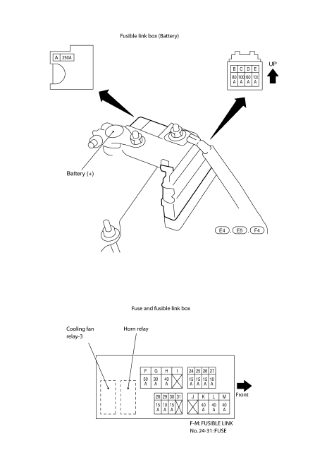
 Fuse block - junction box (J/B)
Terminal Arrangement
...
 IPDM E/R (intelligent power distribution module engine room)
Fuse, Connector and Terminal Arrangement
...
Other materials:
Precaution
PRECAUTIONS
Precaution for Supplemental Restraint System (SRS) "AIR BAG" and
"SEAT BELT PRE-TENSIONER"
The Supplemental Restraint System such as "AIR BAG" and "SEAT BELT
PRE-TENSIONER", used along with a front seat belt, helps to reduce the risk
or severity of injury to the driver and front ...
Door mirror remote control switch
CHANGEOVER SWITCH
CHANGEOVER SWITCH : Description
Changeover switch is integrated into door mirror remote control switch.
Changeover switch has three positions (L, N and R).
It changes door mirror
motor operation by transmitting control signal to automatic drive positioner
control unit.
C ...
Dehumidified defrosting or defogging
1. Press the front
defroster button on.
2. Turn the temperature control dial to set the
maximum temperature to aid in defrosting or
defogging.
To quickly remove ice from the outside of the
windows, use the fan speed
control
buttons to set the fan speed to maximum.
As soon ...
Nissan Maxima Owners Manual
- Illustrated table of contents
- Safety-Seats, seat belts and supplemental restraint system
- Instruments and controls
- Pre-driving checks and adjustments
- Monitor, climate, audio, phone and voice recognition systems
- Starting and driving
- In case of emergency
- Appearance and care
- Do-it-yourself
- Maintenance and schedules
- Technical and consumer information
Nissan Maxima Service and Repair Manual

0.0099