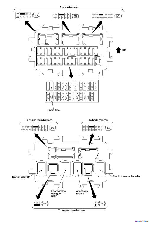
Nissan Maxima Service and Repair Manual: Fuse block - junction box (J/B)
Terminal Arrangement
 Standardized relay
Description
NORMAL OPEN, NORMAL CLOSED AND MIXED TYPE RELAYS
Relays can mainly be divided into three types: normal open, normal closed and
mixed type relays
TYPE OF STANDARDIZED RELAYS
1M * ...
 Fuse, fusible link and relay box
Terminal Arrangement
...
Other materials:
Push-button ignition switch illumination circuit
Description
Provides the power supply and the ground to control the push-button ignition
switch illumination.
Component Function Check
1.CHECK PUSH-BUTTON IGNITION SWITCH ILLUMINATION OPERATION
CONSULT
Turn the ignition switch ON.
Select "ENGINE SW ILLUMI" of BCM (INTELLGENT KEY) active ...
C1156 ST ANG sen com cir
Description
The steering angle sensor is connected to the ABS actuator and electric unit
(control unit) in addition to CAN
lines. CAN (Controller Area Network) is a serial communication line for real
time application. It is an on-vehicle
multiplex communication line with high data communica ...
Diagnosis system (AV control unit)
Diagnosis Description
MULTIFUNCTION SWITCH AND PRESET SWITCH SELF-DIAGNOSIS FUNCTION
The ON/OFF operation (continuity) of each switch in the multifunction switch
and preset switch can be checked.
Self-Diagnosis Mode
Press the BACK switch and the
switch of the 8-direction switches with ...
Nissan Maxima Owners Manual
- Illustrated table of contents
- Safety-Seats, seat belts and supplemental restraint system
- Instruments and controls
- Pre-driving checks and adjustments
- Monitor, climate, audio, phone and voice recognition systems
- Starting and driving
- In case of emergency
- Appearance and care
- Do-it-yourself
- Maintenance and schedules
- Technical and consumer information
Nissan Maxima Service and Repair Manual

0.0074