Nissan Maxima Service and Repair Manual: Removal and installation
BATTERY
Exploded View
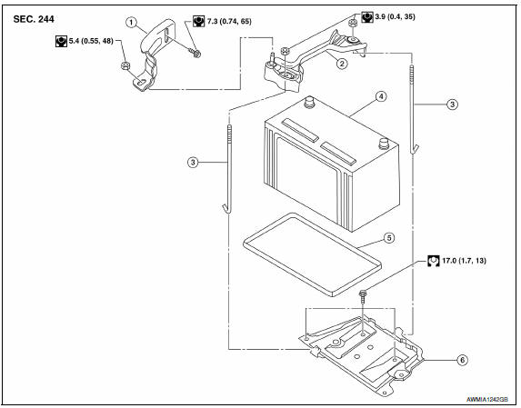
- Upper ECM bracket
- Battery frame
- Battery rods
- Battery
- Battery tray liner
- Battery tray
Removal and Installation (Battery)
REMOVAL
- Loosen battery cable assembly nuts, and disconnect both battery terminals. CAUTION: When disconnecting, disconnect the negative terminal first.
- Remove upper ECM bracket nut and bolt and ECM upper bracket.
- Remove battery rod nuts and battery frame.
- Remove battery.
INSTALLATION
Installation is in the reverse order of removal.
Battery cable assembly nut : 5.4 N*m (0.55 kg-m, 48 in-lb)
CAUTION: When connecting, connect the positive terminal first.
Reset electronic systems as necessary.
Removal and Installation (Battery Tray)
REMOVAL
- Remove battery and battery tray liner. Refer to PG-67, "Removal and Installation (Battery)".
- Remove air cleaner assembly. Refer to EM-24, "Removal and Installation".
- Remove ECM.
- Disconnect transmission control module (TCM). Refer to TM-168, "Removal and Installation".
- Remove the lower ECM bracket.
- Remove current sensor from battery tray.
- Remove the battery tray bolts and battery tray.
INSTALLATION
Installation is in the reverse order of removal.
Reset electronic systems as necessary.
 Preparation
Special Service Tool
The actual shapes of the tools may differ from those illustrated here.
Commercial Service Tool
...
 Service data and specifications (SDS)
Battery
*: Always check with the Parts Department for the latest parts information. ...
Other materials:
Rear door speaker
Removal and Installation
REMOVAL
Remove the rear door finisher. Refer to INT-21, "Removal and
Installation".
Remove the rear door speaker screws (A).
Disconnect the harness connector (B) from the rear door speaker
(1) and remove.
INSTALLATION
Installation is in the reverse orde ...
RGB synchronizing signal circuit
Description
Transmit the RGB synchronizing signal to the display unit so as to
synchronize the RGB image displayed with
AV control unit.
Diagnosis Procedure
1.CHECK CONTINUITY RGB SYNCHRONIZING SIGNAL CIRCUIT
Turn ignition switch OFF.
Disconnect display unit connector M141 and AV co ...
P1723 speed sensor
Description
The secondary speed sensor detects the revolution of
parking gear and generates a pulse signal. The pulse
signal is sent to the TCM, which converts it into vehicle speed.
The primary speed sensor detects the primary pulley revolution speed and sends a
signal to the TCM.
DTC Lo ...
Nissan Maxima Owners Manual
- Illustrated table of contents
- Safety-Seats, seat belts and supplemental restraint system
- Instruments and controls
- Pre-driving checks and adjustments
- Monitor, climate, audio, phone and voice recognition systems
- Starting and driving
- In case of emergency
- Appearance and care
- Do-it-yourself
- Maintenance and schedules
- Technical and consumer information
Nissan Maxima Service and Repair Manual

0.0051