Nissan Maxima Service and Repair Manual: Preparation
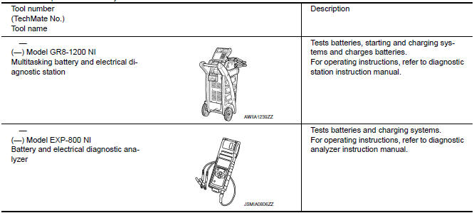
Special Service Tool
The actual shapes of the tools may differ from those illustrated here.
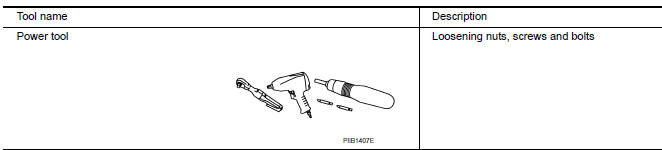
Commercial Service Tool
 Precaution
Precaution for Supplemental Restraint System (SRS) "AIR BAG" and "SEAT
BELT
PRE-TENSIONER"
The Supplemental Restraint System such as "AIR BAG" and "SEAT BELT PRE-TENSIONER",
...
 Removal and installation
BATTERY
Exploded View
Upper ECM bracket
Battery frame
Battery rods
Battery
Battery tray liner
Battery tray
Removal and Installation (Battery)
REMOVAL
Loosen battery cabl ...
Other materials:
Sliding sensor
Description
The sliding sensor is installed to the seat frame.
The pulse signal is input to the driver seat control unit when sliding
is performed.
The driver seat control unit counts the pulse and calculates the sliding
amount of the seat.
Component Function Check
1. CHECK FUNCTIO ...
Microphone
Removal and Installation
REMOVAL
Remove the map lamp assembly. Refer to INL-84, "Removal and
Installation".
Detach the microphone connector (A).
Remove the map lamp covers (1), then remove the map lamp assembly
cover (2).
Release the microphone tabs (A), then remove the micr ...
Jump starting
To start your engine with a booster battery, the
instructions and precautions below must be followed.
WARNING
If done incorrectly, jump starting can
lead to a battery explosion, resulting in
severe injury or death. It could also
damage your vehicle.
Explosive hydrogen gas is always pre ...
Nissan Maxima Owners Manual
- Illustrated table of contents
- Safety-Seats, seat belts and supplemental restraint system
- Instruments and controls
- Pre-driving checks and adjustments
- Monitor, climate, audio, phone and voice recognition systems
- Starting and driving
- In case of emergency
- Appearance and care
- Do-it-yourself
- Maintenance and schedules
- Technical and consumer information
Nissan Maxima Service and Repair Manual

0.0055