Nissan Maxima Service and Repair Manual: Symptom diagnosis
AUDIO SYSTEM
Symptom Table
AUDIO SYSTEM
| Symptoms | Check items | Probable malfunction location |
| The disk cannot be removed. | Audio unit | Malfunction in audio unit.
Refer to AV-73, "Removal and Installation". |
| No sound comes out or the level of the sound is low. | No sound from all speakers |
|
| Only a certain speaker (front door speaker LH, front door speaker RH, tweeter LH, tweeter RH, rear door speaker LH, rear door speaker RH, subwoofer LH, subwoofer RH) does not output sound. |
|
|
| Noise is mixed with audio. | Noise comes out from all speakers. | Malfunction in audio unit.
Refer to AV-73, "Removal and Installation". |
| Noise comes out only from a certain speaker (front door speaker LH, front door speaker RH, tweeter LH, tweeter RH, rear door speaker LH, rear door speaker RH, subwoofer LH, subwoofer RH). |
|
|
| Noise is mixed with radio only (when the vehicle hits a bump or while driving over bad roads) | Poor connector connection of antenna or antenna feeder.
Refer to AV-82, "Location of Antenna". |
|
| No radio reception or poor reception |
|
|
| Buzz/rattle sound from speaker | The majority of buzz/rattle sounds are not indicative of an issue with the speaker, usually something nearby the speaker is causing the buzz/rattle. | Refer to "SQUEAK AND RATTLE TROUBLE DIAGNOSIS" in the appropriate interior trim section. |
RELATED TO HANDS-FREE PHONE
- Before performing diagnosis, confirm that the cellular phone being used by the customer is compatible with the vehicle.
- It is possible that a malfunction is occurring due to a version change of the phone even though the phone is a compatible type. This can be confirmed by changing the cellular phone to another compatible type, and check that it operates normally. It is important to determine whether the cause of the malfunction is the vehicle or the cellular phone.
Check Compatibility
- Make sure the customer's Bluetooth related concern is understood.
- Verify the customer's concern. NOTE: The customer's phone may be required, depending upon their concern.
- Write down the customer's phone brand, model and service provider. NOTE: It is necessary to know the service provider. On occasion, a given phone may be on the approved list with one provider, but may not be on the approved list with other providers.
- Go to "www.nissanusa.com/bluetooth/".
- Using the website's search engine, find out if the customer's phone is on the approved list.
- If the customer's phone is NOT on the approved list: Stop diagnosis here. The customer needs to obtain a Bluetooth phone that is on the approved list before any further action.
- If the feature related to the customer's concern shows as "N" (not compatible): Stop diagnosis here. If the customer still wants the feature to function, they will need to get an approved phone showing the feature as "Y" (compatible) in the "Basic Features".
- If the feature related to the customer's concern shows as "Y" (compatible): Perform diagnosis as per the following table.
| Symptoms | Check items | Probable malfunction location |
| Does not recognize cellular phone connection (no connection is displayed on the display at the guide). | Repeat the registration of cellular phone |
|
| Hands-free phone cannot be established |
|
|
| The other party's voice cannot be heard by hands-free phone | Check the "microphone speaker" in Inspection & Adjustment Mode if sound is heard | |
| Originating sound is not heard by the other party with hands-free phone communication. | Sound operation function is normal | |
| Sound operation function does not work. | Microphone signal circuit malfunction.
Refer to AV-44, "Diagnosis Procedure". |
|
| The system cannot be operated. |
|
Steering switch malfunction.
Replace steering switch. Refer to AV-81, "Removal and Installation". |
Steering switch's  , volume DOWN and
volume UP switches do not work. , volume DOWN and
volume UP switches do not work. |
Steering switch signal circuit malfunction.
Refer to AV-41, "Diagnosis Procedure". |
|
| All steering switches do not work | Steering switch ground circuit malfunction.
Refer to AV-41, "Diagnosis Procedure". |
 does not work.
 NORMAL OPERATING CONDITION
Description
The majority of the audio concerns are the result of outside causes (bad CD, electromagnetic interference, etc.).
NOISE The following noise results from variations in field strength, such as fading noise and multi-path noise, or external noise from trains and other sources. It is not a malfunction.
- - Fading noise: This noise occurs because of variations in the field strength in a narrow range due to mountains or buildings blocking the signal.
- - Multi-path noise: This noise results from the waves sent directly
from the broadcast station arriving at the antenna at a different time
from the waves which reflect off mountains or buildings.
The vehicle itself can be a source of noise, if noise prevention parts or electrical equipment are malfunctioning.
Check if noise is caused and/or changed by engine speed, ignition switch turned to each position, and operation of each piece of electrical equipment, and determine the cause.
NOTE: The source of the noise can be found easily by listening to the noise while removing the fuses of electrical components, one by one.
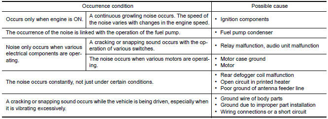
Type of Noise and Possible Cause
RELATED TO HANDS-FREE PHONE
| Symptom | Cause and Counter measure |
| Does not recognize cellular phone connection (No connection is displayed on the display at the guide). | Some Bluetooth enabled cellular phones may not be recognized by
the in-vehicle phone module.
Refer to "RELATED TO HANDS-FREE PHONE (Check Compatibility)" in AV-66, "Symptom Table". |
| Cannot use hands-free phone. |
Customer will not be able to use a hands-free phone under the following conditions:
NOTE: While a cellular phone is connected through the Bluetooth wireless connection, the battery power of the cellular phone may discharge quicker than usual. The Bluetooth Hands-Free Phone System cannot charge cellular phones |
| The other party's voice cannot be heard by hands-free phone. | When the radio wave condition is not ideal or ambient sound is too loud, it may be difficult to hear the other person's voice during a call. |
| Poor sound quality. | Do not place the cellular phone in an area surrounded by metal or far away from the in-vehicle phone module to prevent tone quality degradation and wireless connection disruption. |
 Wiring diagram
MONOCHROME DISPLAY
Wiring Diagram - Without BOSE Audio system
...
 Precaution
PRECAUTIONS
Precaution for Supplemental Restraint System (SRS) "AIR BAG" and
"SEAT BELT PRE-TENSIONER
The Supplemental Restraint System such as "AIR BAG" and "SEAT BELT
PRE-TENSIONER", used alon ...
Other materials:
Rear view camera
Removal and Installation
REMOVAL
Remove the license plate finisher. Refer to EXL-166, "Removal and
Installation".
Remove trunk lid finisher. Refer to INT-36, "Exploded View".
Disconnect the rear view camera connector (B), press the rear
view camera tab (A) and remove the rear view c ...
Under the hood and vehicle
The maintenance items listed here should be
checked periodically (for example, each time you
check the engine oil or refuel).
Battery*: Check the fluid level in each cell. The
fluid should be at the bottom of the filler opening.
Vehicles operated in high temperatures or under
severe condit ...
General maintenance
FOR USA AND CANADA
FOR USA AND CANADA : Explanation of General Maintenance
General maintenance includes those items which should be checked during the
normal day-to-day operation
of the vehicle. They are essential if the vehicle is to continue operating
properly. The owners can perform
che ...
Nissan Maxima Owners Manual
- Illustrated table of contents
- Safety-Seats, seat belts and supplemental restraint system
- Instruments and controls
- Pre-driving checks and adjustments
- Monitor, climate, audio, phone and voice recognition systems
- Starting and driving
- In case of emergency
- Appearance and care
- Do-it-yourself
- Maintenance and schedules
- Technical and consumer information
Nissan Maxima Service and Repair Manual

0.0049