Nissan Maxima Service and Repair Manual: Antenna AMP
Removal and Installation
REMOVAL
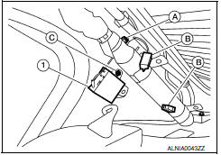
- Remove the rear pillar finisher RH. Refer to INT-23, "Exploded View".
- Detach the antenna amp. harness clip (A).
- Disconnect the harness connectors (B) from the antenna amp. (1).
- Remove the antenna amp. screw (C) and the antenna amp. (1).
INSTALLATION
Installation is in the reverse order of removal.
 Audio antenna
Location of Antenna
Audio unit
Audio unit antenna feeder
In-line connectors M103, M501
Antenna amp.
Window antenna
Window Antenna Repair
ELEMENT CHECK
Attach probe circuit t ...
 Microphone
Removal and Installation
REMOVAL
Remove the front room/map lamp assembly. Refer to INL-84, "Removal
and Installation".
Detach the microphone connector (A).
Remove the front room/map ...
Other materials:
Precaution
Precaution for Supplemental Restraint System (SRS) "AIR BAG" and
"SEAT BELT PRE-TENSIONER"
The Supplemental Restraint System such as "AIR BAG" and "SEAT BELT
PRE-TENSIONER", used along with a front seat belt, helps to reduce the risk
or severity of injury to the driver and front passenger for ...
Telescopic motor
Description
The telescopic motor is installed to the steering column assembly.
The telescopic motor is activated with the automatic drive
positioner control unit.
Compresses the steering column by changing the rotation direction
of telescopic motor.
Component Function Check
1.CHECK ...
Oil filter
Removal and Installation
REMOVAL
Drain engine oil. Refer to LU-9, "Changing Engine Oil".
Remove front fender protector side cover (RH). Refer to EXT-15,
"Exploded View".
Remove the oil filter using Tool (A) as shown.
Tool number : KV10115801 (J-38956)
WARNING: Be ...
Nissan Maxima Owners Manual
- Illustrated table of contents
- Safety-Seats, seat belts and supplemental restraint system
- Instruments and controls
- Pre-driving checks and adjustments
- Monitor, climate, audio, phone and voice recognition systems
- Starting and driving
- In case of emergency
- Appearance and care
- Do-it-yourself
- Maintenance and schedules
- Technical and consumer information
Nissan Maxima Service and Repair Manual

0.0057