Nissan Maxima Service and Repair Manual: Bluetooth control unit
Reference Value
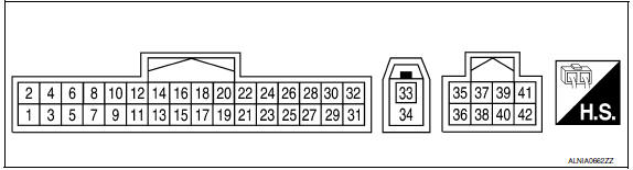
TERMINAL LAYOUT
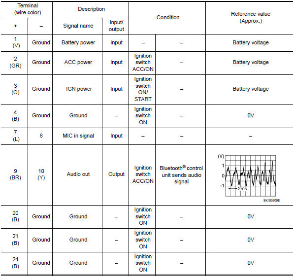
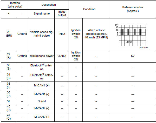
PHYSICAL VALUES
 Satellite radio tuner
Reference Value
PHYSICAL VALUES
...
 Wiring diagram
COLOR DISPLAY
Wiring Diagram - Without BOSE Audio System Without Navigation System
...
Other materials:
Seat belt buckle switch signal circuit
Description
Transmits a seat belt buckle switch LH signal to the combination meter.
Component Function Check
1. CHECK COMBINATION METER INPUT SIGNAL
Start engine.
Monitor seat belt warning lamp while fastening and unfastening the
driver seat belt.
Diagnosis Procedure
Regarding Wiring ...
P2119 electric throttle control actuator
Description
Electric throttle control actuator consists of throttle control motor,
throttle position sensor, etc.
The throttle control motor is operated by the ECM and it opens and closes the
throttle valve.
The throttle position sensor detects the throttle valve position, and the
openi ...
Harness connector
Description
HARNESS CONNECTOR (TAB-LOCKING TYPE)
The tab-locking type connectors help prevent accidental looseness
or disconnection.
The tab-locking type connectors are disconnected by pushing or
lifting the locking tab(s). Refer to the figure
below.
Refer to the next page for desc ...
Nissan Maxima Owners Manual
- Illustrated table of contents
- Safety-Seats, seat belts and supplemental restraint system
- Instruments and controls
- Pre-driving checks and adjustments
- Monitor, climate, audio, phone and voice recognition systems
- Starting and driving
- In case of emergency
- Appearance and care
- Do-it-yourself
- Maintenance and schedules
- Technical and consumer information
Nissan Maxima Service and Repair Manual

0.0063